Mitsubishi Galant. Manual - part 24


  Index      Mitsubishi     Mitsubishi Galant - service repair manual 2001 year


Search            


Content   ..  22  23  24  25   ..


Mitsubishi Galant. Manual - part 24


ENGINE ASSEMBLY

TSB Revision

ENGINE MECHANICAL <2.4L>

11A-15

Required Special Tools:

MB991453: Engine Hanger Assembly

MZ203827: Engine Lifter

REMOVAL SERVICE POINTS

<<A>> POWER STEERING OIL PUMP AND BRACKET 
ASSEMBLY REMOVAL
Remove the power steering oil pump and bracket assembly 
from the engine with the hose attached.

NOTE: Place the removed power steering oil pump in a place 
where it will not be a hindrance when removing and installing 
the engine assembly, and secure it with a cord or wire.

<<B>> A/C COMPRESSOR REMOVAL
Remove the compressor from the compressor bracket with the 
hose still attached.

NOTE: Place the removed A/C compressor where it will not be 
a hindrance when removing and installing the engine assembly, 
and secure it with a cord or wire.

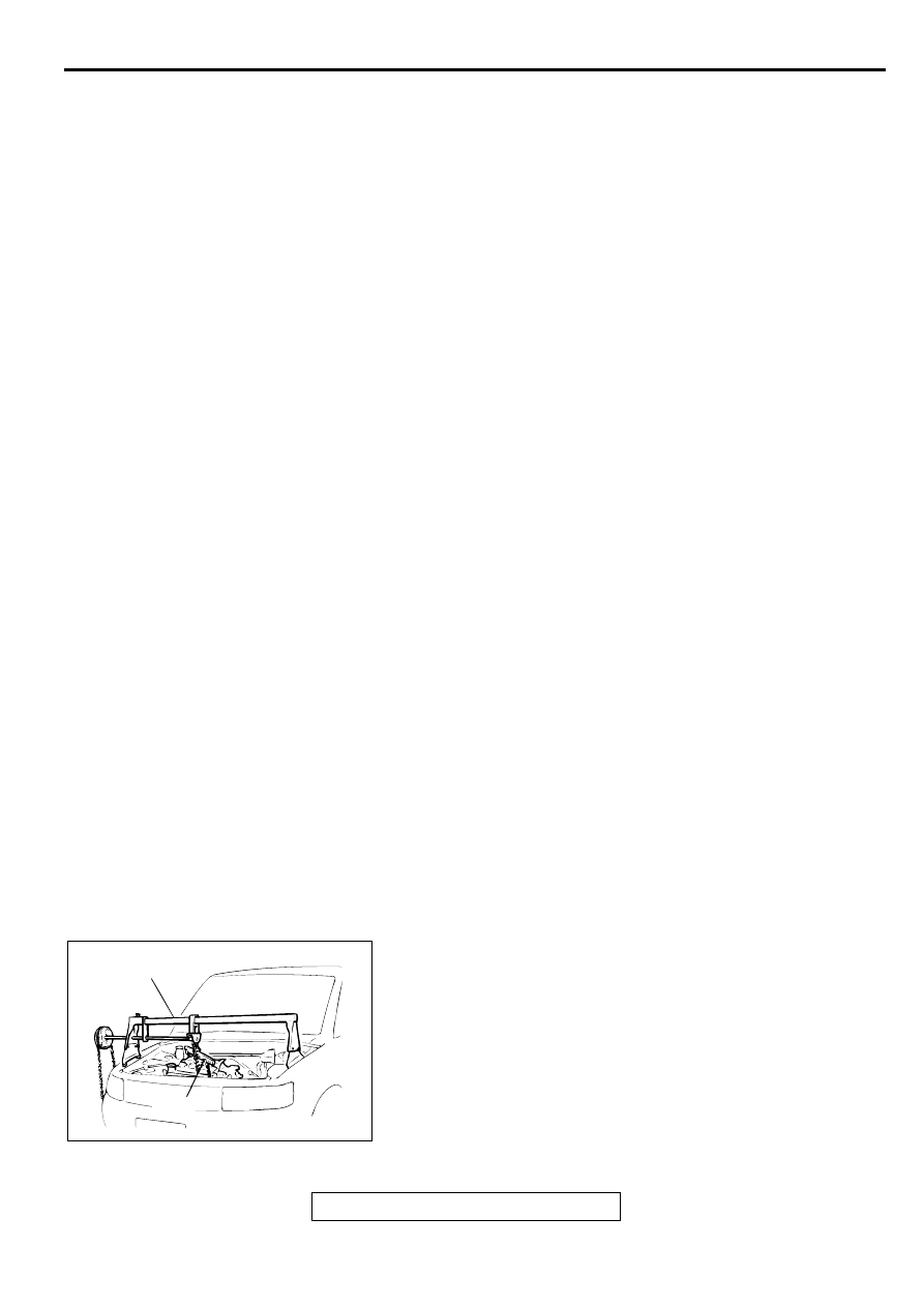
<<C>> ENGINE MOUNT BRACKET REMOVAL
1. Support the engine with a garage jack.
2. Remove special tools MB991453 and MZ203827 which was 

attached when the transaxle assembly was removed.

3. Hold the engine assembly with a chain block or similar tool.

4. Place a garage jack against the engine oil pan with a piece 

of wood in between, jack up the engine so that the weight of 
the engine is no longer being applied to the engine mount 
bracket, and then remove the engine mount bracket.

23. OIL PRESSURE SWITCH 

CONNECTOR

24. DRIVE BELT (POWER STEERING 

OIL PUMP AND A/C 
COMPRESSOR)

25. DRIVE BELT (GENERATOR)
26. CRANKSHAFT POSITION SENSOR 

CONNECTOR

27. POWER STEERING PRESSURE 

SWITCH CONNECTOR

<<A>>

28. POWER STEERING OIL PUMP AND 

BRACKET ASSEMBLY

29. A/C COMPRESSOR ASSEMBLY 

CONNECTOR

<<B>>

30. A/C COMPRESSOR

TRANSAXLE ASSEMBLY
(REFER TO GROUP 23A, 
TRANSAXLE ASSEMBLY 

P.23A-

290

.)

<<C>> >>C<<

31. ENGINE MOUNT BRACKET

>>B<<

32. ENGINE MOUNT STOPPER

<<D>> >>A<<

33. ENGINE ASSEMBLY

AC000127

MZ203827

MB991453

AB

ENGINE ASSEMBLY

TSB Revision

ENGINE MECHANICAL <2.4L>

11A-16

<<D>> ENGINE ASSEMBLY REMOVAL
After checking that all cables, hoses and harness connectors, 
etc., are disconnected from the engine, lift the chain block 
slowly to remove the engine assembly upward from the engine 
compartment.

INSTALLATION SERVICE POINTS

>>A<< ENGINE ASSEMBLY INSTALLATION
Install the engine assembly, checking that the cables, hoses, 
and harness connectors are not clamped.

>>B<< ENGINE MOUNT STOPPER INSTALLATION
Clamp the engine mount stopper so that the arrow points in the 
direction as shown in the diagram.

>>C<< ENGINE MOUNT BRACKET INSTALLATION
1. Place a garage jack against the engine oil pan with a piece 

of wood in between, and install the engine mount bracket 
while adjusting the position of the engine.

2. Support the engine with the garage jack.
3. Remove the chain block and support the engine assembly 

with special tools MB991453 and MZ203827.

>>D<< HIGH-PRESSURE FUEL HOSE INSTALLATION

CAUTION

Do not allow any engine oil to enter the fuel rail.
1. Apply a small amount of new engine oil to the O-ring.

2. While turning the high-pressure fuel hose to the right and 

left, install it to the fuel rail, while being careful not to 
damage the O-ring. After installing, check that the hose 
turns smoothly.

3. If the hose does not turn smoothly, the O-ring is probably 

being clamped. Disconnect the high-pressure fuel hose and 
check the O-ring for damage. Replace if necessary.

4. Re-insert the fuel rail and confirm the hose turns smoothly.

AC000128

ENGINE SIDE

ENGINE MOUNT
BRACKET

ENGINE MOUNT
STOPPER

ARROW

AB

AC000127

MZ203827

MB991453

AB

AC000129 AB

FUEL RAIL

HIGH-PRESSURE
FUEL HOSE

O-RING

CAMSHAFT AND CAMSHAFT OIL SEAL

TSB Revision

ENGINE MECHANICAL <2.4L>

11A-17

C A M SH A FT A N D  C A M SH A FT O IL SEA L

REMOVAL AND INSTALLATION

M1112001900110

Required Special Tools:

MB990767: End Yoke Holder

MB998713: Crankshaft Oil Seal Installer

MD998443: Auto-lash Adjuster Holder

MD998719: Crankshaft Pulley Holder Pin

Pre-removal and Post-installation Operation

Air Cleaner Removal and Installation (Refer to GROUP 
15, Air Cleaner 

P.15-4

.)

Timing Belt Removal and Installation (Refer to 

P.11A-30

.)

AC000130

2

1

9.8 N·m
87 in-lb

3.4 N·m
30 in-lb

5

4

3

6

7

13

10

N

N

11

12

28 – 34 N·m
21 – 25 ft-lb

88 N·m
65 ft-lb

8

9

14 N·m
124 in-lb

22 N·m
16 ft-lb

AC

9

13

ENGINE OIL

LIP
SECTION

6

SEALANT:
     MITUBISHI GENUINE PART 
     NO.MD970389OR EQUIVALENT

Ø 3 mm
(0.1 in)

CAM SECTION
AND JOURNAL
SECTION

CAMSHAFT REMOVAL STEPS

1.

SPARK PLUG CABLE

2.

IGNITION COIL

3

.

PCV HOSE

4.

BREATHER HOSE

5.

ROCKER COVER

6.

CAMSHAFT POSITION 
SENSOR SUPPORT

7.

CAMSHAFT POSITION 
SENSING CYLINDER

<<A>>

>>C<<

8.

CAMSHAFT SPROCKET

10. SPARK PLUG GUIDE OIL SEAL

<<B>>

>>A<<

11. ROCKER ARM AND SHAFT 

ASSEMBLY (INTAKE SIDE)

<<B>>

>>A<<

12. ROCKER ARM AND SHAFT 

ASSEMBLY (EXHAUST SIDE)

13. CAMSHAFT

CAMSHAFT OIL SEAL 
REMOVAL STEPS

<<A>>

>>C<<

8.

CAMSHAFT SPROCKET

>>B<<

9.

CAMSHAFT OIL SEAL

CAMSHAFT REMOVAL STEPS 

CAMSHAFT AND CAMSHAFT OIL SEAL

TSB Revision

ENGINE MECHANICAL <2.4L>

11A-18

REMOVAL SERVICE POINTS

<<A>> CAMSHAFT SPROCKET REMOVAL
1. Use special tools MB990767 and MD998719 to loosen the 

camshaft sprocket securing bolt.

2. Remove the camshaft sprocket.

<<B>> ROCKER ARM AND SHAFT ASSEMBLY REMOVA
1. Install special tool MD998443 as shown in the illustration so 

that the lash adjusters will not fall out.

CAUTION

Never disassemble the rocker arm and shaft assembly.
2. Loosen the rocker arm and shaft assembly mounting bolt, 

and then remove the rocker arm and shaft assembly with the 
bolt still attached.

INSTALLATION SERVICE POINTS

>>A<< ROCKER ARM AND SHAFT ASSEMBLY 
INSTALLATION
1. Temporarily tighten the rocker shaft with the bolt so that all 

rocker arms do not push the valves.

2. Fit the rocker shaft spring from the above and position it so 

that it is right angles to the plug guide.

NOTE: Install the rocker shaft spring before installing the 
rocker arm and rocker arm shaft on the exhaust side.

3. Tighten the rocker arm and shaft assembly mounting bolt to 

the specified torque.

Tightening torque: 28 

−−−−

 34 N

⋅⋅⋅⋅

m (21 

−−−−

 25 ft-lb)

4. Remove special tool MD998443.

ACX00301

MB990767

MD998719

AC

ACX00331AB

MB998443

ACX00378

PLUG GUIDE

ROCKER SHAFT SPRING

ROCKER SHAFT 
SPRING

PLUG GUIDE

AB


Content   ..  22  23  24  25   ..