Mitsubishi Galant. Manual - part 22
ON VEHICLE SERVICE
TSB Revision
ENGINE MECHANICAL <2.4L>
11A-7
•
Diagnosis output
•
Timing belt cover and crankshaft position sensor installation
conditions
•
Crankshaft sensing blade condition
CAUTION
If the actuator test is not canceled, the forced drive will
continue for 27 minutes. Driving in this state could lead to
engine failure.
9. Press the clear key on scan tool MB991502 (select forced
drive stop mode), and cancel the actuator test.
10.Check that the actual ignition timing is at the standard value.
Standard value: Approximately 10
°°°°
BTDC
NOTE: Ignition timing fluctuates about
±
7
°
Before Top Dead
Center, even under normal operating condition.
NOTE: It is automatically further advanced by about 5
°
to
10
°
Before Top Dead Center at higher altitudes.
IDLE MIXTURE CHECK
M1111002100095
Required Special Tool:
MB991502: Scan Tool (MUT-II)
1. Before inspection, set vehicles in the following condition:
•
Engine coolant temperature: 80
−
95
°
C
(176
- 203
°
F)
•
Lights and all accessories: OFF
•
Transaxle: "P" range
CAUTION
To prevent damage to scan tool MB991502, always turn the
ignition switch to the "LOCK" (OFF) position before
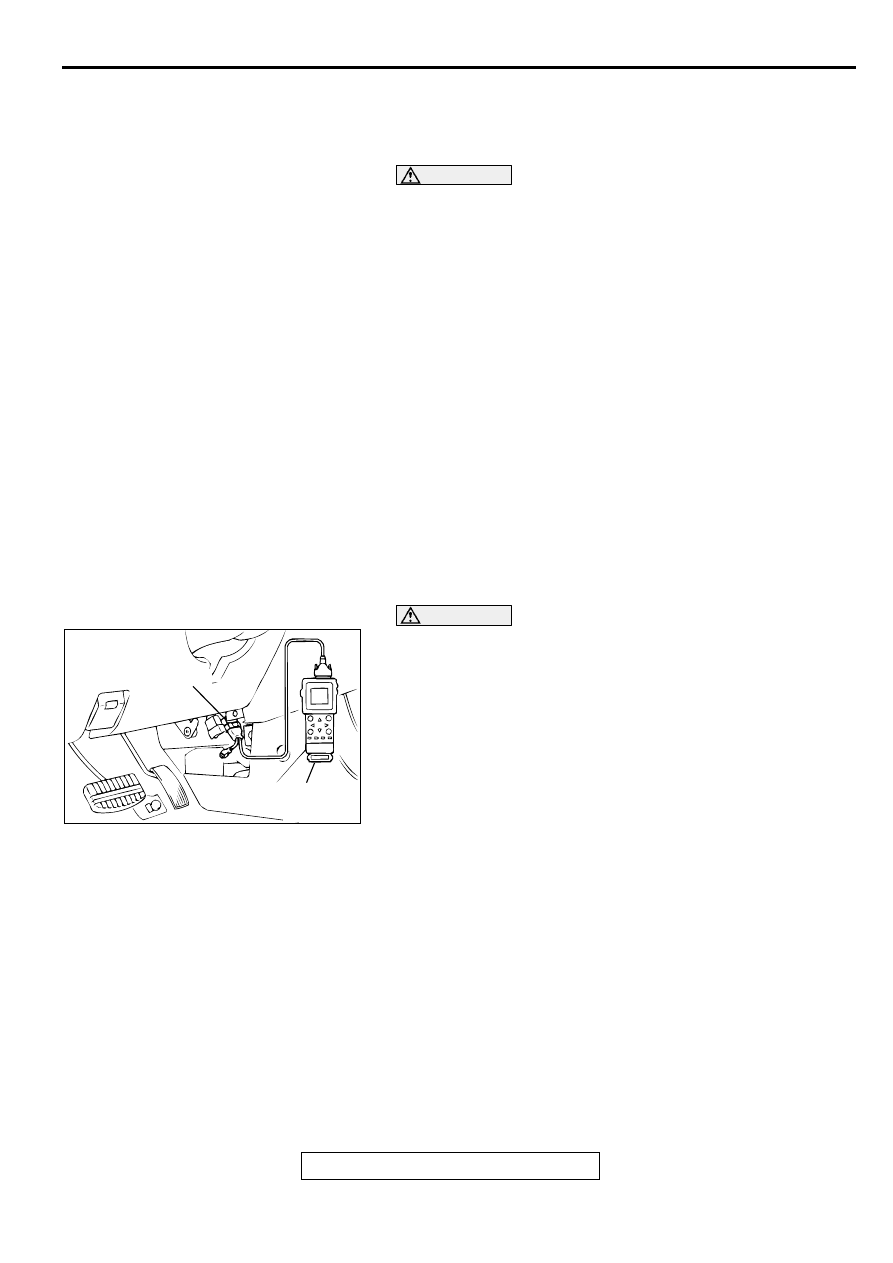
connecting or disconnecting scan tool MB991502.
2. Connect scan tool MB991502 to the data link connector.
3. Check that the basic ignition timing is within the standard
value.
Standard value: 5
°°°°
BTDC
±±±±
3
°°°°
4. Start the engine and increase the engine speed to 2,500 r/
min for 2 minutes.
5. Set the CO, HC tester.
6. Check the CO contents and the HC contents at idle.
Standard value:
CO contents: 0.5% or less
HC contents: 100 ppm or less
7. If the CO and HC contents do not remain inside the standard
value, check the following items:
NOTE: Replace the catalytic converter when the CO and HC
contents do not remain inside the standard value, even
though the result of the inspection is normal for all items.
•
Diagnosis output
•
Closed-loop control (When the closed-loop control is carried
out normally, the output signal of the heated oxygen sensor
changes between 0
−
400 mV and 600
−
1,000 mV at idle.)
•
Fuel pressures
AC003081 AB
16 PIN
MB991502