Mitsubishi Galant. Manual - part 6
VEHICLE IDENTIFICATION
TSB Revision
GENERAL <BODY AND CHASSIS>
00-21
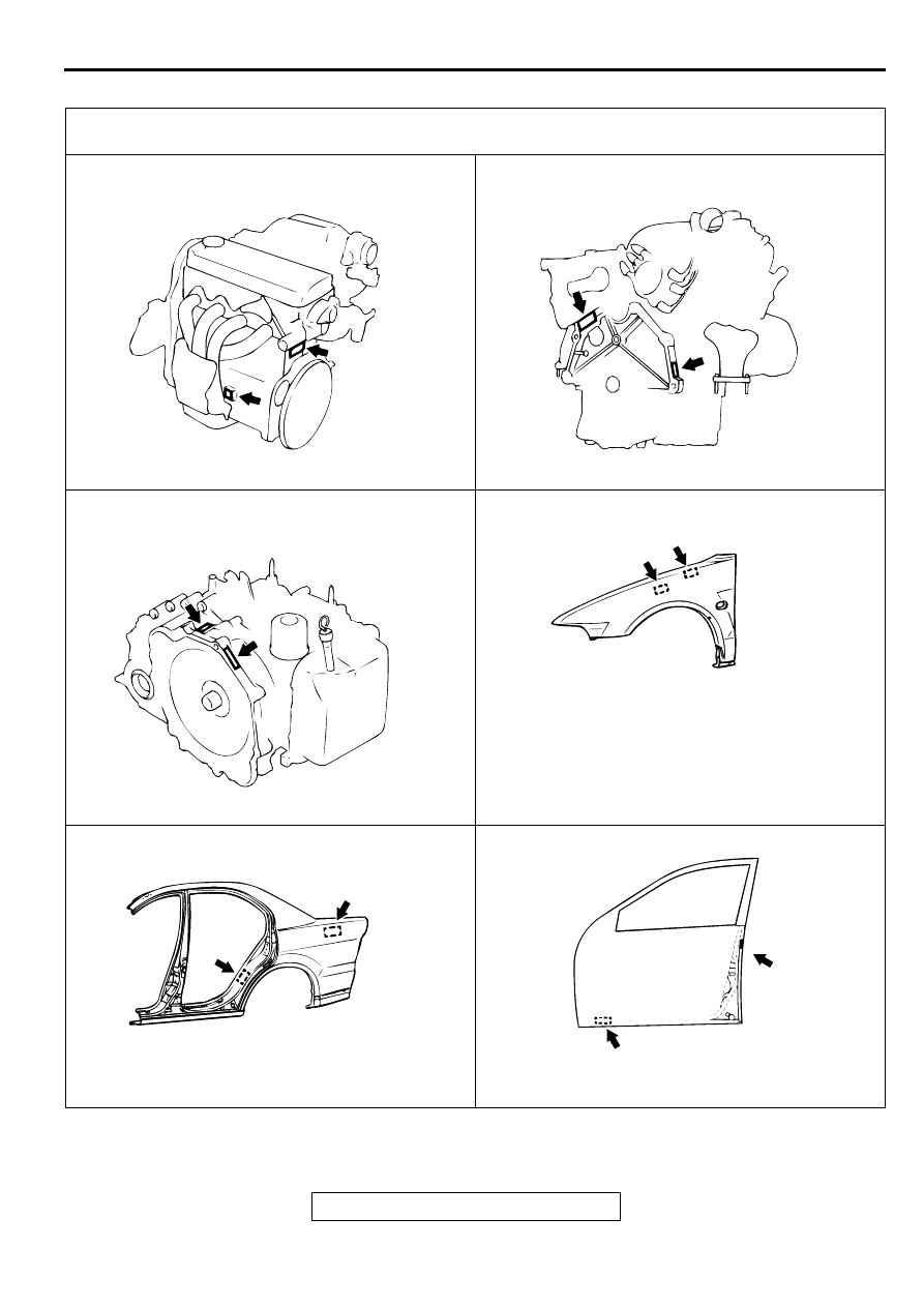
LOCATIONS
THEFT PROTECTION LABEL TARGET AREA (A: FOR ORIGINAL EQUIPMENT PARTS, B: FOR RE-
PLACEMENT PARTS)
AC000058
ENGINE
<4G64>
AB
A
B
AC000061
ENGINE
<6G72>
AB
B
A
AC000060
AUTOMATIC TRANSAXLE
AB
A
B
AC004807
FENDER
B
A
AB
THE ILLUSTRATION INDICATES LEFT OUTER SIDE
RIGHT SIDE IS SYMMETRICALLY OPPOSITE.
AC004808
QUARTER PANEL OUTER
THE ILLUSTRATION INDICATES LEFT OUTER SIDE.
RIGHT SIDE IS SYMMETRICALLY OPPOSITE.
A
B
AB
AC004809 AB
FRONT DOOR
A
B
THE ILLUSTRATION INDICATES LEFT OUTER SIDE.
RIGHT SIDE IS SYMMETRICALLY OPPOSITE.