Mitsubishi Galant 9G. Manual - part 900


  Index      Mitsubishi     Mitsubishi Galant 9G - service repair manual


Search            


Content   ..  898  899  900  901   ..


Mitsubishi Galant 9G. Manual - part 900


MULTIPORT FUEL INJECTION (MFI) DIAGNOSIS

TSB Revision

MULTIPORT FUEL INJECTION (MFI) <2.4L ENGINE>

13A-1042

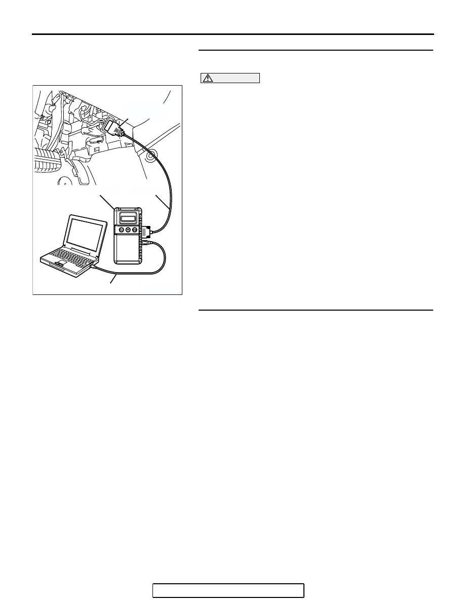
STEP 3. Using scan tool MB991958, check data list item 21: 
Engine Coolant Temperature Sensor.

CAUTION

To prevent damage to scan tool MB991958, always turn the 
ignition switch to the "LOCK" (OFF) position before con-
necting or disconnecting scan tool MB991958.
(1) Connect scan tool MB991958 to the data link connector.
(2) Start the engine and run at idle.
(3) Check the following items in the data list. Refer to Data List 

Reference Tabl

P.13A-1083

a. Item 21 Engine Coolant Temperature Sensor.

(4) Turn the ignition switch to the "LOCK" (OFF) position.
Q: Is the sensor operating properly?

YES : Go to Step 4.
NO :  Repair and replace. Then confirm that the malfunction 

symptom is eliminated.

STEP 4. Check the cooling system.
Refer to GROUP 14, Engine Cooling Diagnosis 

P.14-3

.

Q: Is the cooling system normal?

YES : Replace the PCM.
NO :  Replace it. Then confirm that the malfunction 

symptom is eliminated.

AK303804AB

MB991910

DATA LINK
CONNECTOR

MB991824

MB991827

MULTIPORT FUEL INJECTION (MFI) DIAGNOSIS

TSB Revision

MULTIPORT FUEL INJECTION (MFI) <2.4L ENGINE>

13A-1043

INSPECTION PROCEDURE 28: Power supply system and ignition switch-IG system.

6

2 3

4 5 6

1

1

3

2

4 5

1 2 3

4 5 6

7

12

11

10

14

13

9

8

1 2

3 4 5

14

15

8 9

12 13

6 7

10 11
16 17

22

21

23 24 25

26 27 28 29

30 31 32 33 34

35 36 37 38

39 40 41 42 43

52

51

53 54 55 56

57

58 59 60 61 62

63

64 65 66 67 68 69

70

71 72 73 74 75

76

77 78 79 80 81 82

83

1

2

3

4

AK303922

BLA

CK-

WHITE

BLA

CK-ORANGE

RED-WHITE

RED

RED

RED

SKY BLUE

RED-

WHITE

RED-

WHITE

RED-

WHITE

RED-

WHITE

WHITE

BLA

CK

BATTERY

R

IG2

ST

LOCK

ACC

IG1

C-308

C-215

MU801331

IGNITION
SWITCH

2

6

1

JUNCTION  BLOCK

43

42

MFI
RELAY

B-17X

A-14

(MU802755)

1

2

4

3

52

BATTERY
BACKUP

64

51

POWER
SOURCE

BLA

CK

29

POWERTRAIN CONTROL
MODULE (PCM)

GROUNDING
CONNECTOR

B-20

B-21

5

9

20A

25

17

7.5A

RELAY
BOX

Power Supply and Ignition Switch-IG Circuit

C-214

MU801857

A-13

3

2

MULTIPORT FUEL INJECTION (MFI) DIAGNOSIS

TSB Revision

MULTIPORT FUEL INJECTION (MFI) <2.4L ENGINE>

13A-1044

.

CIRCUIT OPERATION

• Battery positive voltage is applied to the MFI 

relay (terminals No. 1, No. 2).

• When the ignition switch is turned to the "ON" 

position, the battery positive voltage is applied to 
the PCM (terminal No. 43). When the battery pos-
itive voltage is applied, the PCM turns the power 
transistor in the PCM "ON" and grounds the MFI 
relay coil. With this, the MFI relay turns "ON" and 
the battery positive voltage is supplied to the 
PCM (terminals No. 51, No. 64) from the MFI 
relay (terminal No. 4).

• A battery positive voltage is constantly supplied 

to the PCM (terminal No. 42) as the backup 

power.

AK303241

CONNECTORS: B-20, 21

PCM

AB

AIR CLEANER

B-20

B-21 (B)

AK303872AB

A-13 (GR)

CONNECTOR: A-13

AK303803AB

CONNECTOR: B-17X

MFI RELAY

B-17X

AK303923AB

CONNECTOR: C-308

C-308

AK303924AB

CONNECTOR: C-214

C-214

AK303925AB

CONNECTOR: C-215

C-215

AK303901AB

CONNECTOR: A-14

A-14 (GR)

MULTIPORT FUEL INJECTION (MFI) DIAGNOSIS

TSB Revision

MULTIPORT FUEL INJECTION (MFI) <2.4L ENGINE>

13A-1045

• The PCM (terminals No. 25, No. 29) is grounded 

to the vehicle body.

.

TROUBLESHOOTING HINTS (The most 
likely causes for this code to be set are:) 

• Malfunction of the ignition switch.

• Malfunction of the MFI relay.

• Improper connector contact, open or shorted har-

ness wire.

• Disconnected PCM ground wire.

• Malfunction of the PCM.

DIAGNOSIS

STEP 1. Check harness connector B-17X at MFI relay for 
damage.
Q: Is the connector in good condition?

YES : Go to Step 2.
NO :  Repair or replace it. Refer to GROUP 00E, Harness 

Connector Inspection 

P.00E-2

. Then confirm that the 

malfunction symptom is eliminated.

AK303806

2

1

3

4

AB

CONNECTOR: B-17X

B-17X

RELAY BOX
TRIANGLE 
MARK

HARNESS CONNECTOR:
COMPONENT SIDE


Content   ..  898  899  900  901   ..