Mitsubishi Galant 9G. Manual - part 899


  Index      Mitsubishi     Mitsubishi Galant 9G - service repair manual


Search            


Content   ..  897  898  899  900   ..


Mitsubishi Galant 9G. Manual - part 899


MULTIPORT FUEL INJECTION (MFI) DIAGNOSIS

TSB Revision

MULTIPORT FUEL INJECTION (MFI) <2.4L ENGINE>

13A-1038

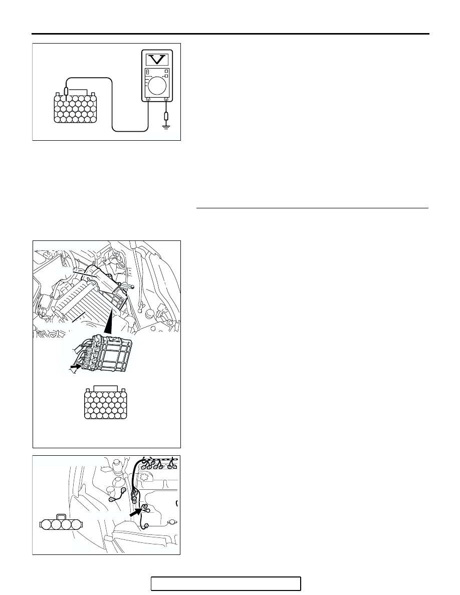
(3) Measure the voltage between terminal No. 132 and ground.

NOTE: Vehicle for Canada, the headlight, taillight, etc. 
remain lit even when the lighting switch is in "OFF" position 
but this is no problem for checks.

a. Engine: warming up
b. Radiator fan: stopped

c. Headlight switch: OFF to ON

d. Rear defogger switch: OFF to ON
e. Stoplight switch: OFF to ON

• Voltage rises.

(4) Turn the ignition switch to the "LOCK" (OFF) position.
Q: Is the measured voltage within the specified range?

YES : Go to Step 2.
NO :  Replace the generator. Then confirm that the 

malfunction symptom is eliminated.

STEP 2. Check harness connector B-23 at PCM connector 
and harness connector B-116 at generator connector for 
damage.
Q: Is the harness connector in good condition?

YES : Go to Step 3.
NO :  Repair or replace it. Refer to GROUP 00E, Harness 

Connector Inspection 

P.00E-2

. Then confirm that the 

malfunction symptom is eliminated.

127 126 125 124 123 122 121

133 132 131 130 129 128

140 139 138 137 136 135 134

146 145 144 143 142 141

153 152 151 150 149 148 147

AK203183AB

POWER PLANT ECU 
CHECK HARNESS 
CONNECTOR 

127 126 125 124 123 122 121

133 132 131 130 129 128

140 139 138 137 136 135 134

146 145 144 143 142 141

153 152 151 150 149 148 147

AK303058

HARNESS CONNECTOR: 
COMPONENT SIDE

CONNECTOR: B-23

B-23

PCM

AB

AIR CLEANER

AK303884

2

1

3

4

AB

CONNECTOR: B-116

B-116 (GR)

HARNESS 
CONNECTOR: 
COMPONENT SIDE

MULTIPORT FUEL INJECTION (MFI) DIAGNOSIS

TSB Revision

MULTIPORT FUEL INJECTION (MFI) <2.4L ENGINE>

13A-1039

STEP 3. Check for open circuit and short circuit to ground 
and harness damage between generator connector B-116 
(terminal No. 1) and PCM connector B-23 (terminal No. 
132).
Q: Is the harness wire in good condition?

YES : Replace the PCM. Then confirm that the malfunction 

symptom is eliminated.

NO :  Repair it. Then confirm that the malfunction symptom 

is eliminated.

AK303884

2

1

3

4

AB

CONNECTOR: B-116

B-116 (GR)

HARNESS 
CONNECTOR: 
COMPONENT SIDE

127 126 125 124 123 122 121

133 132 131 130 129 128

140 139 138 137 136 135 134

146 145 144 143 142 141

153 152 151 150 149 148 147

AK303058

HARNESS CONNECTOR: 
COMPONENT SIDE

CONNECTOR: B-23

B-23

PCM

AB

AIR CLEANER

MULTIPORT FUEL INJECTION (MFI) DIAGNOSIS

TSB Revision

MULTIPORT FUEL INJECTION (MFI) <2.4L ENGINE>

13A-1040

INSPECTION PROCEDURE 27: Fans (radiator fan, A/C condenser fan) are inoperative

.

COMMENT

• The fan control relay is controlled by the power 

transistor inside the PCM turning "ON" and 
"OFF".

.

TROUBLESHOOTING HINTS (The most 
likely causes for this code to be set are:) 

• Malfunction of the fan control relay.

• Malfunction of the fan condenser fan relay.

• Malfunction of the radiator fan relay.

• Malfunction of the condenser fan motor.

• Malfunction of the radiator fan motor.

• Improper connector contact, open or shorted har-

ness wire.

• PCM failed. 

RED-WHITE

AK303260

5

POWERTRAIN
CONTROL 
MODULE (PCM)

RADIATOR
FAN RELAY

WHITE-RED

WHITE-RED

CONDENSER
FAN RELAY

BLUE-ORANGE

10

FAN CONTROL
RELAY

B-19

1 2 3 4

5 6 7

8 9 10 11

12 13 14

15 16 17 18

AK303147

CONNECTOR: B-19

PCM

AB

AIR CLEANER

B-19 (B)

MULTIPORT FUEL INJECTION (MFI) DIAGNOSIS

TSB Revision

MULTIPORT FUEL INJECTION (MFI) <2.4L ENGINE>

13A-1041

DIAGNOSIS

Required Special Tools:

• MB991958: Scan tool (MUT-III Sub Assembly)

• MB991824: V.C.I.

• MB991827: USB Cable

• MB991910: Main Harness A

STEP 1. Check harness connector B-19 at PCM for 
damage.
Q: Is the harness connector in good condition?

YES :  Go to Step 2.
NO :  Repair or replace it. Refer to GROUP 00E, Harness 

Connector Inspection 

P.00E-2

. Then confirm that the 

malfunction symptom is eliminated.

STEP 2. Check the fan condition.
(1) Disconnect the B-19 at PCM connector.
(2) Turn the ignition switch to the "ON" position.
(3) Check the fan condition.

• When the terminal No.10 is grounded by the jumper 

cable, the radiator and condenser fans should run.

• When the terminal No.10 is grounded first and then both 

of the terminal No.10 and No.5 are grounded next, 
check that the rotation speed of fan is higher than the 
rotation speed when the terminal No.10 is grounded.

(4) Turn the ignition switch to the "LOCK" (OFF) position.
Q: Is the fan condition normal?

YES : Go to Step 3.
NO :  Refer to GROUP 14, Symptom Char

P.14-3

.

AK303153

4 3 2 1

7 6 5

9 8

11 10

14 13 12

18 17 16 15

CONNECTOR: B-19

PCM

AB

AIR CLEANER

HARNESS CONNECTOR: 
COMPONENT SIDE

B-19 (B)

AK303257

1 2 3 4

5 6 7

8 9 10 11

12 13 14

15 16 17 18

B-19 HARNESS CONNECTOR:
COMPONENT SIDE

AB

AK303259

1 2 3 4

5 6 7

8 9 10 11

12 13 14

15 16 17 18

B-19 HARNESS CONNECTOR:
COMPONENT SIDE

AB


Content   ..  897  898  899  900   ..