Mitsubishi Galant 9G. Manual - part 749
MULTIPORT FUEL INJECTION (MFI) DIAGNOSIS
TSB Revision
MULTIPORT FUEL INJECTION (MFI) <2.4L ENGINE>
13A-438
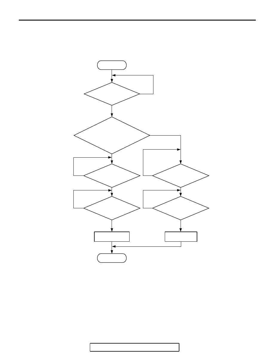
DTC SET CONDITIONS
Logic Flow Chart
.
Check Conditions
• The engine coolant temperature − intake air tem-
perature is 5
°C (41°F) or less when the engine is
started.
• The engine coolant temperature is between
−10°C (14°F) and 36°C (97°F) when the engine is
started.
• The engine coolant temperature is higher than
60
°C (140°F).
• Maximum vehicle speed is higher than 30 km/h
(19 mph) after the engine starting sequence has
been completed.
Judgement Criteria
• The fuel tank temperature − engine coolant tem-
perature is 15
°C (59°F) or more when the engine
is started.
START
NO
YES
YES
YES
YES
NO
NO
NO
END
NO
YES
YES
NO
MALFUNCTION
GOOD
MONITORING
CONDITIONS
“FUEL TEMP. AT
ENGINE START” -
“ENGINE COOLANT TEMP. AT
ENGINE START”
> 15˚C (59˚F)
ENGINE
COOLANT TEMP.
> =60˚C (140˚F)
ENGINE
COOLANT TEMP.
> =60˚C (140˚F)
MAX.
VEHICLE SPEED
> 30km/h (19mph)
MAX.
VEHICLE SPEED
> 30km/h (19mph)
AK401537