Mitsubishi Galant 9G. Manual - part 750


  Index      Mitsubishi     Mitsubishi Galant 9G - service repair manual


Search            


Content   ..  748  749  750  751   ..


Mitsubishi Galant 9G. Manual - part 750


MULTIPORT FUEL INJECTION (MFI) DIAGNOSIS

TSB Revision

MULTIPORT FUEL INJECTION (MFI) <2.4L ENGINE>

13A-442

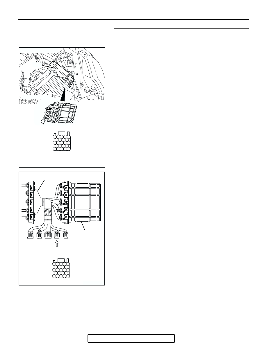
STEP 6. Measure the sensor supply voltage at PCM 
connector B-20 by using power plant ECU check harness 
special tool MB991923.
(1) Disconnect the all PCM connectors and connect power 

plant ECU check harness special tool MB991923 between 
the separated connectors.

(2) Turn the ignition switch to the "ON" position.

AK303092

25

21

24 23 22

29 28 27 26

34 33 32 31 30

38 37 36 35

43 42 41 40 39

CONNECTOR: B-20

B-20

PCM

AB

HARNESS CONNECTOR: 
COMPONENT SIDE

AIR CLEANER

AK203002

25

21

24 23 22

29 28 27 26

34 33 32 31 30

38 37 36 35

43 42 41 40 39

AB

POWER PLANT ECU 
CHECK HARNESS CONNECTOR

MB991923

PCM

MULTIPORT FUEL INJECTION (MFI) DIAGNOSIS

TSB Revision

MULTIPORT FUEL INJECTION (MFI) <2.4L ENGINE>

13A-443

(3) Measure the voltage between terminal No. 41 and ground.

• When fuel tank temperature is 0°C (32°F), voltage 

should be between  2.7 and 3.1 volts.

• When fuel tank temperature is 20°C (68°F), voltage 

should be between 2.1 and 2.5 volts.

• When fuel tank temperature is 40°C (104°F), voltage 

should be between 1.6 and 2.0 volts.

• When fuel tank temperature is 80°C (176°F), voltage 

should be between 0.8 and 1.2 volts.

(4) Turn the ignition switch to the "LOCK" (OFF) position.
Q: Is the measured voltage normal?

YES : Go to Step 7.
NO :  Go to Step 8.

STEP 7. Check harness connector B-20 at PCM for 
damage.
Q: Is the harness connector in good condition?

YES :  Check harness connector C-25 at intermediate 

connector for damage, and repair or replace as 
required. Refer to GROUP 00E, Harness Connector 
Inspection 

P.00E-2

. If intermediate connector is in 

good condition, repair harness wire between fuel tank 
temperature sensor connector D-18 (terminal No. 3) 
and PCM connector B-20 (terminal No. 41) because 
of open circuit. Then go to Step 12.

NO :  Repair or replace it. Refer to GROUP 00E, Harness 

Connector Inspection 

P.00E-2

. Then go to Step 12.

25

21

24 23 22

29 28 27 26

34 33 32 31 30

38 37 36 35

43 42 41 40 39

AK203168AB

POWER PLANT ECU 
CHECK HARNESS 
CONNECTOR 

AK303092

25

21

24 23 22

29 28 27 26

34 33 32 31 30

38 37 36 35

43 42 41 40 39

CONNECTOR: B-20

B-20

PCM

AB

HARNESS CONNECTOR: 
COMPONENT SIDE

AIR CLEANER

MULTIPORT FUEL INJECTION (MFI) DIAGNOSIS

TSB Revision

MULTIPORT FUEL INJECTION (MFI) <2.4L ENGINE>

13A-444

STEP 8. Check harness connector B-20 at PCM for 
damage.
Q: Is the harness connector in good condition?

YES : Go to Step 9.
NO :  Repair or replace it. Refer to GROUP 00E, Harness 

Connector Inspection 

P.00E-2

. Then go to Step 12.

AK303092

25

21

24 23 22

29 28 27 26

34 33 32 31 30

38 37 36 35

43 42 41 40 39

CONNECTOR: B-20

B-20

PCM

AB

HARNESS CONNECTOR: 
COMPONENT SIDE

AIR CLEANER

MULTIPORT FUEL INJECTION (MFI) DIAGNOSIS

TSB Revision

MULTIPORT FUEL INJECTION (MFI) <2.4L ENGINE>

13A-445

STEP 9. Check for short circuit to ground between fuel 
tank temperature sensor connector D-18 (terminal No. 3) 
and PCM connector B-20 (terminal No. 41).

NOTE: Check harness after checking intermediate connector 
C-25. If intermediate connector is damaged, repair or replace it. 
Refer to GROUP 00E, Harness Connector Inspection 

P.00E-2

Then go to Step 12. 
Q: Is the harness wire in good condition?

YES : Replace the PCM. Then go to Step 12.
NO :  Repair it. Then go to Step 12.

AK303840

1

2

3

4

5

SERVICE
HOLE

AB

CONNECTOR: D-18

D-18 (GR)

HARNESS 
CONNECTOR: 
COMPONENT SIDE

AK303092

25

21

24 23 22

29 28 27 26

34 33 32 31 30

38 37 36 35

43 42 41 40 39

CONNECTOR: B-20

B-20

PCM

AB

HARNESS CONNECTOR: 
COMPONENT SIDE

AIR CLEANER


Content   ..  748  749  750  751   ..