Mitsubishi Galant 9G. Manual - part 671


  Index      Mitsubishi     Mitsubishi Galant 9G - service repair manual


Search            


Content   ..  669  670  671  672   ..


Mitsubishi Galant 9G. Manual - part 671


MULTIPORT FUEL INJECTION (MFI) DIAGNOSIS

TSB Revision

MULTIPORT FUEL INJECTION (MFI) <2.4L ENGINE>

13A-126

DIAGNOSIS

Required Special Tools:

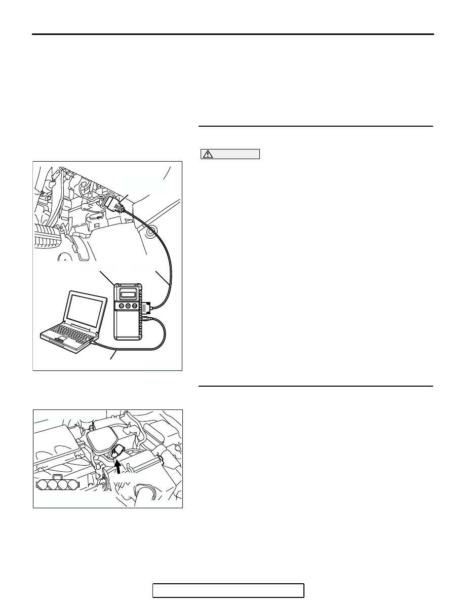
• MB991958: Scan Tool (MUT-III Sub Assembly)

• MB991824: V.C.I.

• MB991827: USB Cable

• MB991910: Main Harness A

• MB991923: Power Plant ECU Check Harness

STEP 1. Using scan tool MB991958, check data list item 13: 
Intake Air Temperature Sensor.

CAUTION

To prevent damage to scan tool MB991958, always turn the 
ignition switch to the "LOCK" (OFF) position before con-
necting or disconnecting scan tool MB991958.
(1) Connect scan tool MB991958 to the data link connector.
(2) Turn the ignition switch to the "ON" position.
(3) Set scan tool MB991958 to the data reading mode for item 

13, Intake Air Temperature Sensor.

• The intake air temperature and temperature shown with 

the scan tool should approximately match.

(4) Turn the ignition switch to the "LOCK" (OFF) position.
Q: Is the sensor operating properly?

YES : It can be assumed that this malfunction is intermittent. 

Refer to GROUP 00, How to Use 
Troubleshooting/Inspection Service Points 

− How to 

Cope with Intermittent Malfunctions 

P.00-14

.

NO :  Go to Step 2.

STEP 2. Check harness connector B-10 at the intake air 
temperature sensor for damage.
Q: Is the harness connector in good condition?

YES : Go to Step 3.
NO :  Repair or replace it. Refer to GROUP 00E, Harness 

Connector Inspection 

P.00E-2

. Then go to Step 11.

AK303804AB

MB991910

DATA LINK
CONNECTOR

MB991824

MB991827

AK303805

2

1

3

4

AB

CONNECTOR: B-10

B-10 (GR)

HARNESS CONNECTOR:
COMPONENT SIDE

MULTIPORT FUEL INJECTION (MFI) DIAGNOSIS

TSB Revision

MULTIPORT FUEL INJECTION (MFI) <2.4L ENGINE>

13A-127

STEP 3. Check the intake air temperature sensor.
(1) Disconnect the intake air temperature sensor connector 

B-10.

(2) Measure the resistance between intake air temperature 

sensor side connector terminal No. 1 and No. 4.

• There should be continuity. (0.30 − 20 kΩ)

Q: Is the measured resistance between 0.30 and 20 k

?

YES : Go to Step 4.
NO :  Replace the mass airflow sensor. Then go to Step 11.

STEP 4. Measure the sensor supply voltage at intake air 
temperature sensor harness side connector B-10.
(1) Disconnect the connector B-10 and measure at the harness 

side.

(2) Turn the ignition switch to the "ON" position.

(3) Measure the voltage between terminal No. 1 and ground.

• Voltage should be between 4.5 and 4.9 volts.

(4) Turn the ignition switch to the "LOCK" (OFF) position.
Q: Is the measured voltage between 4.5 and 4.9 volts?

YES : Go to Step 8.
NO :  Go to Step 5.

AK303805

2

1

3

4

AB

CONNECTOR: B-10

B-10 (GR)

HARNESS CONNECTOR:
COMPONENT SIDE

1

2

3 4

AK203041

INTAKE AIR TEMPERATURE
SENSOR CONNECTOR

AB

AK303805

2

1

3

4

AB

CONNECTOR: B-10

B-10 (GR)

HARNESS CONNECTOR:
COMPONENT SIDE

AK203042

2

1

3

4

AC

B-10 HARNESS 
CONNECTOR: 
COMPONENT SIDE

MULTIPORT FUEL INJECTION (MFI) DIAGNOSIS

TSB Revision

MULTIPORT FUEL INJECTION (MFI) <2.4L ENGINE>

13A-128

STEP 5. Measure the sensor supply voltage at PCM 
connector B-22 by using power plant ECU check harness 
special tool MB991923.
(1) Disconnect the all PCM connectors and connect power 

plant ECU check harness special tool MB991923 between 
the separated connectors.

(2) Disconnect the intake air temperature sensor connector 

B-10.

(3) Turn the ignition switch to the "ON" position.

AK303016

104

96

94

95

93 92 91

99 98 97

103 102 101 100

108 107 106 105

113 112 111 110 109

CONNECTOR: B-22

B-22 (B)

PCM

AB

HARNESS CONNECTOR: 
COMPONENT SIDE

AIR CLEANER

MULTIPORT FUEL INJECTION (MFI) DIAGNOSIS

TSB Revision

MULTIPORT FUEL INJECTION (MFI) <2.4L ENGINE>

13A-129

(4) Measure the voltage between terminal No. 107 and ground.

• Voltage should be between 4.5 and 4.9 volts.

(5) Turn the ignition switch to the "LOCK" (OFF) position.
Q: Is the measured voltage between 4.5 and 4.9 volts?

YES : Go to Step 6.
NO :  Go to Step 7.

AK202956

104

96

94

95

93 92 91

99 98 97

103 102 101 100

108 107 106 105

113 112 111 110 109

AB

POWER PLANT ECU 
CHECK HARNESS CONNECTOR

MB991923

PCM

104

96

94

95

93 92 91

99 98 97

103 102 101 100

108 107 106 105

113 112 111 110 109

AK203043AB

POWER PLANT ECU 
CHECK HARNESS 
CONNECTOR 


Content   ..  669  670  671  672   ..