Mitsubishi Galant 9G. Manual - part 443


  Index      Mitsubishi     Mitsubishi Galant 9G - service repair manual


Search            


Content   ..  441  442  443  444   ..


Mitsubishi Galant 9G. Manual - part 443


TRACTION CONTROL SYSTEM (TCL) DIAGNOSIS

TSB Revision

TRACTION CONTROL SYSTEM (TCL)

13D-40

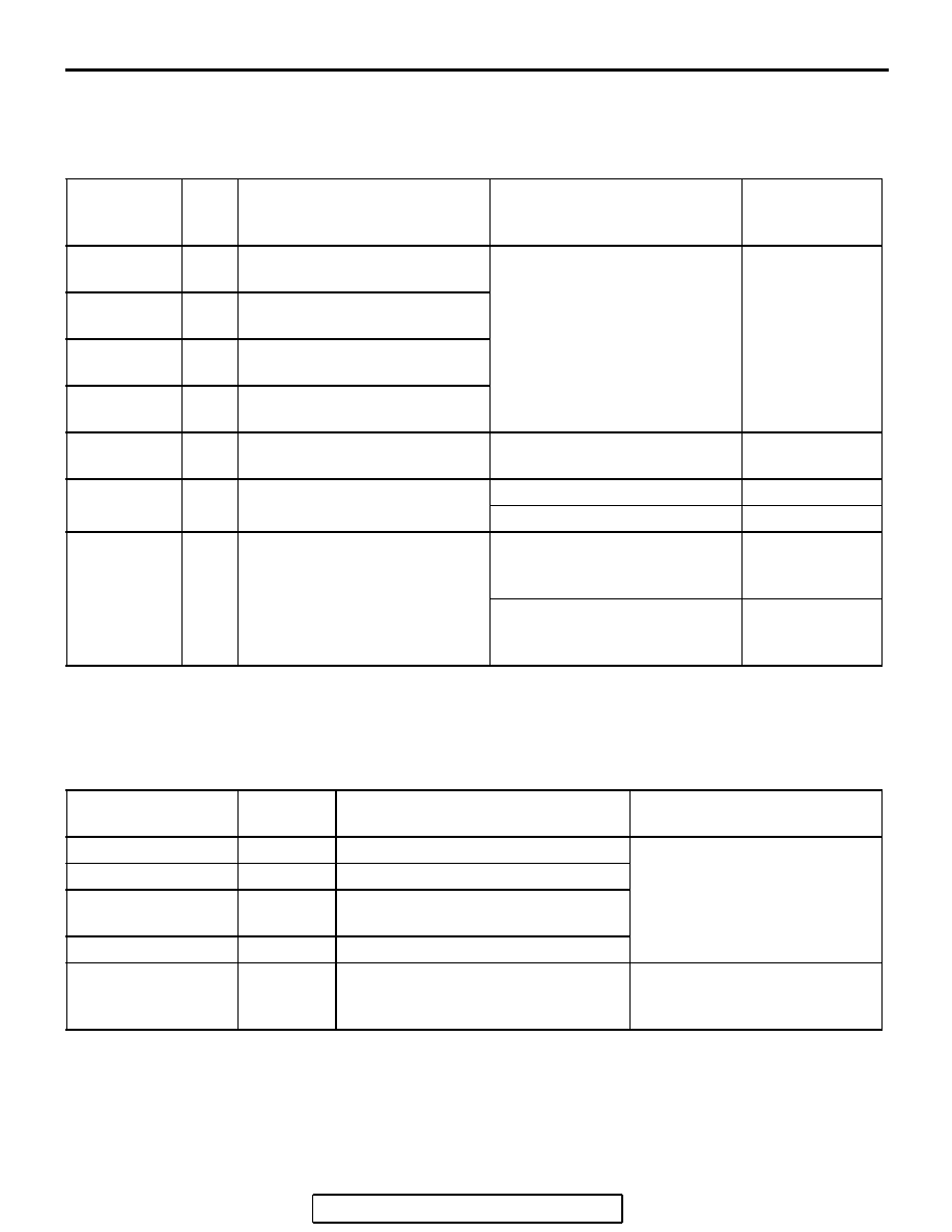
DATA LIST REFERENCE TABLE

M1136003500071

The following items can be read by the scan tool 
from the ABS/TCL-ECU input data. (Refer to 

P.13D-3

).

NOTE: Since the TCL is controlled with the same ABS/TCL-ECU used to control the ABS, the stoplight switch 
check item (No.6) used only for the ABS also appear.

ACTUATOR TEST REFERENCE TABLE

M1136003600067

The scan tool activates the following actuators for 
testing. (Refer to 

P.13D-3

).

NOTE: Since the TCL is controlled with the same ABS/TCL-ECU used to control the ABS, the FR, FL, RR or 
RL Wheel ABS Drive testing items (No.01 to 04) used only for the ABS also appear.

MUT-III 
SCAN TOOL 
DISPLAY

ITEM 
NO.

CHECK ITEM

CHECKING REQUIREMENTS NORMAL 

VALUE

FR wheel 
speed sensor

01

Front right wheel speed sensor Drive the vehicle

Vehicle speeds 
displayed on the 
speedometer 
and scan tool are 
identical.

FL wheel 
speed sensor

02

Front left wheel speed sensor

RR wheel 
speed sensor

03

Rear right wheel speed sensor

RL wheel 
speed sensor

04

Rear left wheel speed sensor

Battery 
voltage

05

ABS/TCL-ECU power supply 
voltage

Ignition switch power supply 
voltage

Battery positive 
voltage

Stoplight 
switch*

06

Stoplight switch

Depress the brake pedal.

ON

Release the brake pedal.

OFF

TCL mode

35

TCL operation

When the TCL outputs the 
operation permission signal 
during driving

ON

When the TCL outputs the 
operation inhibition signal 
during driving

OFF

MUT-III SCAN TOOL 
DISPLAY

ITEM NO.

CHECK ITEM

PARTS TO BE ACTIVATED

FR wheel ABS Drive* 01

Solenoid valve for front right wheel

Solenoid valves and pump 
motors in the hydraulic unit 
(simple inspection mode)

FL wheel ABS Drive* 02

Solenoid valve for front left wheel

RR wheel ABS 
Drive*

03

Solenoid valve for rear right wheel

RL wheel ABS Drive* 04

Solenoid valve for rear left wheel

Engine TCL Drive

09

TCL operation check

Outputs the engine torque 
control signal (engine torque = 
0) to PCM for three seconds.

TRACTION CONTROL SYSTEM (TCL) DIAGNOSIS

TSB Revision

TRACTION CONTROL SYSTEM (TCL)

13D-41

CHECK AT ABS/TCL-ECU TERMINAL VOLTAGE

M1136003800072

TERMINAL VOLTAGE CHECK CHART

.

Required Special Tools:
MB991970: ABS Check Harness
MB991223: Harness Set
1. Disconnect the ABS/TCL-ECU connector A-02 and connect 

special tool MB991970 between the ABS/TCL-ECU and the 
body-side harness connector. Then use special tool 
MB991970 to measure the voltages between terminal 2 and 
each terminal.

2. The terminal layouts are shown in the illustrations below.
NOTE: Do not measure terminal voltage for approximately 
three seconds after the ignition switch is turned "ON." The 
ABS/TCL-ECU performs the initial check during that period.

AC305209AB

A-02 (GR)

CONNECTOR: A-02 

A-02 HARNESS CONNECTOR:

COMPONENT SIDE

AC211156AC

ABS/TCL-ECU

A-02 HARNESS
CONNECTOR

MB991970

INSPECTION
HARNESS
CONNECTOR

TRACTION CONTROL SYSTEM (TCL) DIAGNOSIS

TSB Revision

TRACTION CONTROL SYSTEM (TCL)

13D-42

CONNECTOR 
TERMINAL NO

SIGNAL

CHECKING REQUIREMENT

NORMAL 
CONDITION

6

TCL switch

Ignition 
switch: "ON" 

When the TCL switch is not 
pressed.

Battery positive 
voltage

When the TCL switch is 
pressed.

1 V or less

20

ABS/TCL-ECU power 
supply

Ignition switch: "ON" 

Battery positive 
voltage

Ignition switch: "START"

1 V or less

TRACTION CONTROL SYSTEM (TCL) DIAGNOSIS

TSB Revision

TRACTION CONTROL SYSTEM (TCL)

13D-43

RESISTANCE AND CONTINUITY BETWEEN 
HARNESS-SIDE CONNECTOR TERMINALS

.

Required Special Tools:
MB991970: ABS Check Harness
MB991223: Harness Set
1. Disconnect the ABS/TCL-ECU connector A-02 and connect 

special tool MB991970 to the A-02 body-side harness 
connector. Then turn the ignition switch to the "LOCK" (OFF) 
position and checking resistance and continuity.

2. Check the resistance and continuity between the terminals 

indicated in the table below.

3. The terminal layout is shown in the illustration.

AC305209AB

A-02 (GR)

CONNECTOR: A-02 

A-02 HARNESS CONNECTOR:

COMPONENT SIDE

AC211160AD

ABS/TCL-ECU

A-02 HARNESS
CONNECTOR

MB991970

INSPECTION
HARNESS
CONNECTOR


Content   ..  441  442  443  444   ..