Mitsubishi Galant 9G. Manual - part 406


  Index      Mitsubishi     Mitsubishi Galant 9G - service repair manual


Search            


Content   ..  404  405  406  407   ..


Mitsubishi Galant 9G. Manual - part 406


ON-VEHICLE SERVICE

TSB Revision

BASIC BRAKE SYSTEM

35A-16

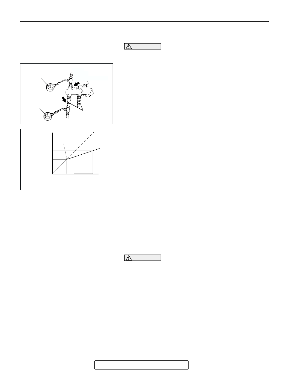
PROPORTIONING VALVE FUNCTION TEST 
<VEHICLES WITHOUT ABS>

M1351001100346

CAUTION

The proportioning valves are installed  independently for 
the right and left brake lines. Always measure each valve.
1. Connect two pressure gauges to the output port of the 

master cylinder and output port of the proportioning valve.

2. Bleed the brake line and the pressure gauges (Refer to 

P.35A-16

).

3. Depress the brake pedal gradually. Then check that the split 

point, where the output fluid pressure begins to drop in 
proportion to the output fluid pressure, is at the standard 
value.

Standard value: 3.68 

 4.17 MPa (534  605 psi)

4. Depress the brake pedal more strongly than at the above 

step. Then check that the output fluid pressure is at the 
standard value when the input fluid pressure is 7.85 MPa 
(1,139 psi).

Standard value: 5.24 

 5.74 MPa (760  833 psi)

5. Measure each output fluid pressure at both valves, and 

check that the difference between the two is at the limit 
value or less.

Limit: 0.5 MPa (73 psi)

6. If the measured pressure exceeds the limit, replace the 

proportioning valve.

BLEEDING

M1351001400455

CAUTION

Use only brake fluid DOT 3 or DOT 4. Never mix the speci-
fied brake fluid with other fluid as it will influence the brak-
ing performance significantly.

.

MASTER CYLINDER BLEEDING

The master cylinder used has no check valve, so if bleeding is 
carried out by the following procedure, bleeding of air from the 
brake pipeline will become easier. (When brake fluid is not con-
tained in the master cylinder).
1. Fill the reserve tank with brake fluid.
2. Keep the brake pedal depressed.

AC006221AD

PROPORTIONING
VALVE

OUTPUT PORT

PRESSURE GAUGE (A)

PRESSURE GAUGE (B)

OUTPUT PORT

AC006222 AB

SPLIT POINT

INPUT PRESSURE
<PRESSURE GAUGE (A)>

OUTPUT
PRESSURE
<PRESSURE
GAUGE (B)>

ON-VEHICLE SERVICE

TSB Revision

BASIC BRAKE SYSTEM

35A-17

3. Have another person cover the master cylinder outlet with a 

finger.

4. With the outlet still closed, release the brake pedal.
5. Repeat steps 2 

− 4 three or four times to fill the inside of the 

master cylinder with brake fluid.

.

BRAKE LINE BLEEDING

Start the engine and bleed the air in the sequence shown in the 
figure.

AC306134AB

OUTLET

OUTLET

OUTLET

VEHICLES WITH ABS

VEHICLES WITHOUT ABS

AC006223AB

4

2

1

3

4, 6

2

1, 3

5

VEHICLES WITH ABS

VEHICLES WITHOUT ABS

ON-VEHICLE SERVICE

TSB Revision

BASIC BRAKE SYSTEM

35A-18

BRAKE FLUID LEVEL SENSOR CHECK

M1351009100403

The brake fluid level sensor is in good condition if there is no 
continuity when the float surface is above "MIN" and if there is 
continuity when the float surface is below "MIN".

DISC BRAKE PAD CHECK AND REPLACEMENT

M1351002300398

NOTE: The brake pads (LH wheel) have indicators that contact 
the brake disc when the brake pad thickness becomes 2 mm 
(0.08 inch), and emit a squealing sound to warn the driver.

CAUTION

• Whenever a pad must be replaced, replace both LH and 

RH wheel pads as a set to prevent the vehicle from pull-
ing to one side when braking.

• If there is a significant difference in the thicknesses of 

the pads on the left and right sides, check the sliding 
condition of the piston and slide  pins.

1. Check the brake pad thickness through the caliper body 

check port.

Standard value: 10.0 mm (0.39 inch)
Minimum limit: 2.0 mm (0.08 inch)

AC305546

AC000879

WHEN NEW

WHEN WORN

AB

PAD

WEAR INDICATOR

BRAKE
DISC

AC305371

AB

<FRONT>

AC305372

AB

<REAR>

ON-VEHICLE SERVICE

TSB Revision

BASIC BRAKE SYSTEM

35A-19

CAUTION

Do not wipe off the special grease that is on the lock pin. 
Do not contaminate the lock pin.
2. Remove the lock pin bolt <Front> or lock pin and brake hose 

clamp <Rear>. Pivot the caliper assembly and hold it with 
wires.

AC305371

AC

<FRONT>

AC307348

AB

<REAR>


Content   ..  404  405  406  407   ..