Content .. 1601 1602 1603 1604 ..
Mitsubishi Galant 9G. Manual - part 1603
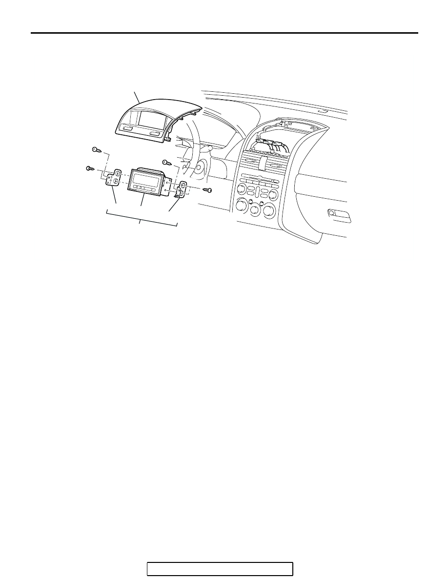
MULTI-CENTER DISPLAY
TSB Revision
CHASSIS ELECTRICAL
54A-284
<MIDDLE GRADE TYPE>
AC307018
1
4
3
4
2
AB
REMOVAL STEPS
1.
CONSOLE METER HOOD (REFER TO
GROUP 52A, INSTRUMENT PANEL
ASSEMBLY
2.
MULTI-CENTER DISPLAY ASSEMBLY
3.
MULTI-CENTER DISPLAY
4.
MULTI-CENTER DISPLAY BRACKET
REMOVAL STEPS (Continued)