Mitsubishi Galant 9G. Manual - part 1577


  Index      Mitsubishi     Mitsubishi Galant 9G - service repair manual


Search            


Content   ..  1575  1576  1577  1578   ..


Mitsubishi Galant 9G. Manual - part 1577


RADIO WITH CD PLAYER

TSB Revision

CHASSIS ELECTRICAL

54A-180

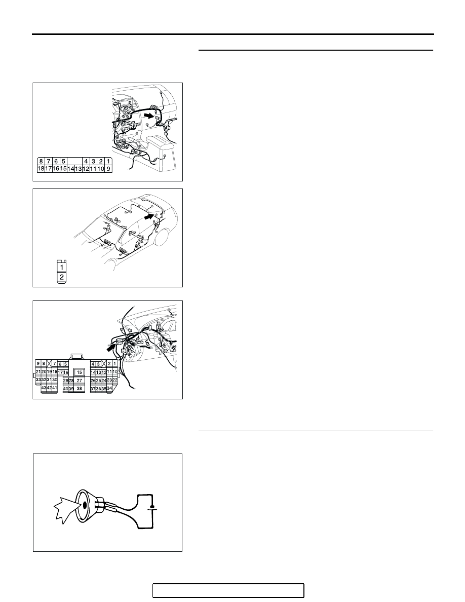
STEP 16. Check the wiring harness between rear speaker 
(LH) connector D-12 (terminals 1 and 2) and audio 
amplifier connector C-113 (terminals 2 and 10).

NOTE: Also check intermediate connector C-28 for loose, cor-
roded, or damaged terminals, or terminals pushed back in the 
connector. If intermediate connector C-28 is damaged, repair or 
replace the connectors as described in GROUP 00E, Harness 
Connector Inspection 

P.00E-2

.

Q: Is the wiring harness between the rear speaker (LH) 

connector D-12 (terminals 1 and 2) and audio amplifier 
connector C-113 (terminals 2 and 10) in good condition?
YES : 
Replace the audio amplifier. The rear speaker (LH) 

should sound.

NO :  Repair the wiring harness. The rear speaker (LH) 

should sound.

STEP 17. Check the rear speaker (RH).
(1) Remove the rear speaker (RH). Refer to 

P.54A-209

.

(2) Check that the rear speaker (RH) generates noise when a 

five-volt voltage is applied on the rear speaker (RH) 
terminal.

Q: Is the rear speaker (RH) generating noise?

YES : Go to Step 18.
NO :  Replace the rear speaker (RH). The rear speaker 

(RH) should sound.

AC305233CC

CONNECTOR: C-113

HARNESS SIDE

AC305268

AU

CONNECTOR: D-12

HARNESS SIDE

AC305231AE

CONNECTOR:C-28

ACX01868AB

5V

RADIO WITH CD PLAYER

TSB Revision

CHASSIS ELECTRICAL

54A-181

STEP 18. Check rear speaker (RH) connector D-09 and 
audio amplifier connector C-113 for loose, corroded or 
damaged terminals, or terminals pushed back in the 
connector.
Q: Are harness connectors D-09 and C-113 in good 

condition?
YES : 
Go to Step 19.
NO :  Repair or replace the component(s). Refer to GROUP 

00E, Harness Connector Inspection 

P.00E-2

. The 

rear speaker (RH) should sound.

AC305233CC

CONNECTOR: C-113

HARNESS SIDE

AC305268

AS

CONNECTOR: D-09

HARNESS SIDE

RADIO WITH CD PLAYER

TSB Revision

CHASSIS ELECTRICAL

54A-182

STEP 19. Check the wiring harness between rear speaker 
(RH) connector D-09 (terminals 1 and 2) and audio 
amplifier connector C-113 (terminals 9 and 1).

NOTE: Also check intermediate connector C-13 for loose, cor-
roded, or damaged terminals, or terminals pushed back in the 
connector. If intermediate connector C-13 is damaged, repair or 
replace the connectors as described in GROUP 00E, Harness 
Connector Inspection 

P.00E-2

.

Q: Is the wiring harness between rear speaker (RH) 

connector D-09 (terminals 1 and 2) and audio amplifier 
connector C-113 (terminals 9 and 1) in good condition?
YES : 
Replace the audio amplifier. The rear speaker (RH) 

should sound.

NO :  Repair the wiring harness. The rear speaker (RH) 

should sound.

AC305234

CONNECTORS: C-13, C-113

C-13

HARNESS SIDE

C-113

C-113

C-13

BB

AC305268

AS

CONNECTOR: D-09

HARNESS SIDE

RADIO WITH CD PLAYER

TSB Revision

CHASSIS ELECTRICAL

54A-183

INSPECTION PROCEDURE 8: Noise is Present while Moving (AM).

STEP 1. Ask the driver about the noise.
(1) Find out the following information from the owner.
(2) Place where the noise occurs.
(3) Locality conditions (valley, mountain, etc).
(4) Name and frequency of stations affected by 

noise.

Q: What type of noise is detected, vehicle noise or 

external noise?
Vehicle noise : 

It may not be possible to prevent 

noise if the signal is weak. Go to step 2.

External noise : 

In almost all cases, prevention on 

the receiver side is next to impossible when 
the signal is weak. Go to Step 4.

STEP 2. Ask the driver about the location where 
the noise occurs.

Q: Does the noise occur when entering or near a 

particular structure (building, tunnel, mountain, 
etc)?
YES : 

Go to Step 3.

NO : 

Go to Step 4.

STEP 3. Check if the noise can be eliminated by 
adjusting the radio.
(1) Adjust the radio as follows.
(2) Change to a different station with a stronger 

signal. This will boost the systems resistance to 
outside interference.

(3) Suppress high tones to reduce noise.

Q: Has the noise been eliminated?

YES : 

The noise has now been eliminated. Inform 
the customer that it is normal to hear noise 
while receiving a weak station.

NO : 

Go to Step 4.

STEP 4. Check for the noise.

Q: Does noise still exist? 

YES : 

If there is still more noise than on other 
similar radio’s find out the type of noise. Ask 
the owner for the name and frequency of the 
affected stations, and consult with the radio 
manufacturer service center.

NO : 

System is operating normally.

INSPECTION PROCEDURE 9: Noise is Present while Moving (FM).

.

DIAGNOSIS

NOTE: FM waves have the same properties as light, 
and can be deflected and blocked. FM signal recep-
tion is severely degraded in the shadow of obstruc-
tions such as buildings or mountains. An FM receiver 
will then only receive a reflected signal.

1. The signal becomes weak as the distance from 

the station's transmission antenna increases. The 
signal strength received depends on the signal 
strength of the transmitting station and intervening 
obstructions such as buildings and hills. Generally 
speaking, the area of good reception is 
approximately 20 

− 25 km (12 − 16 miles) for 

stereo reception, and 30 

− 40 km (19 − 25 miles) 

for monaural reception.

ACX01869

10kW
OUTPUT FM
BROAD CAST

FOR STEREO:
20 - 25 km
(12 - 16 miles)

FOR  MONAURAL:
30 - 40 km (19 - 25 miles)

FOR  HOME STEREO:
80 - 90 km (50 - 56 miles)

MALTIPATH INTERFERENCE

FIRST FADING
INTERFERENCE

AC


Content   ..  1575  1576  1577  1578   ..