Mitsubishi Galant 9G. Manual - part 1568


  Index      Mitsubishi     Mitsubishi Galant 9G - service repair manual


Search            


Content   ..  1566  1567  1568  1569   ..


Mitsubishi Galant 9G. Manual - part 1568


RADIO WITH CD PLAYER

TSB Revision

CHASSIS ELECTRICAL

54A-144

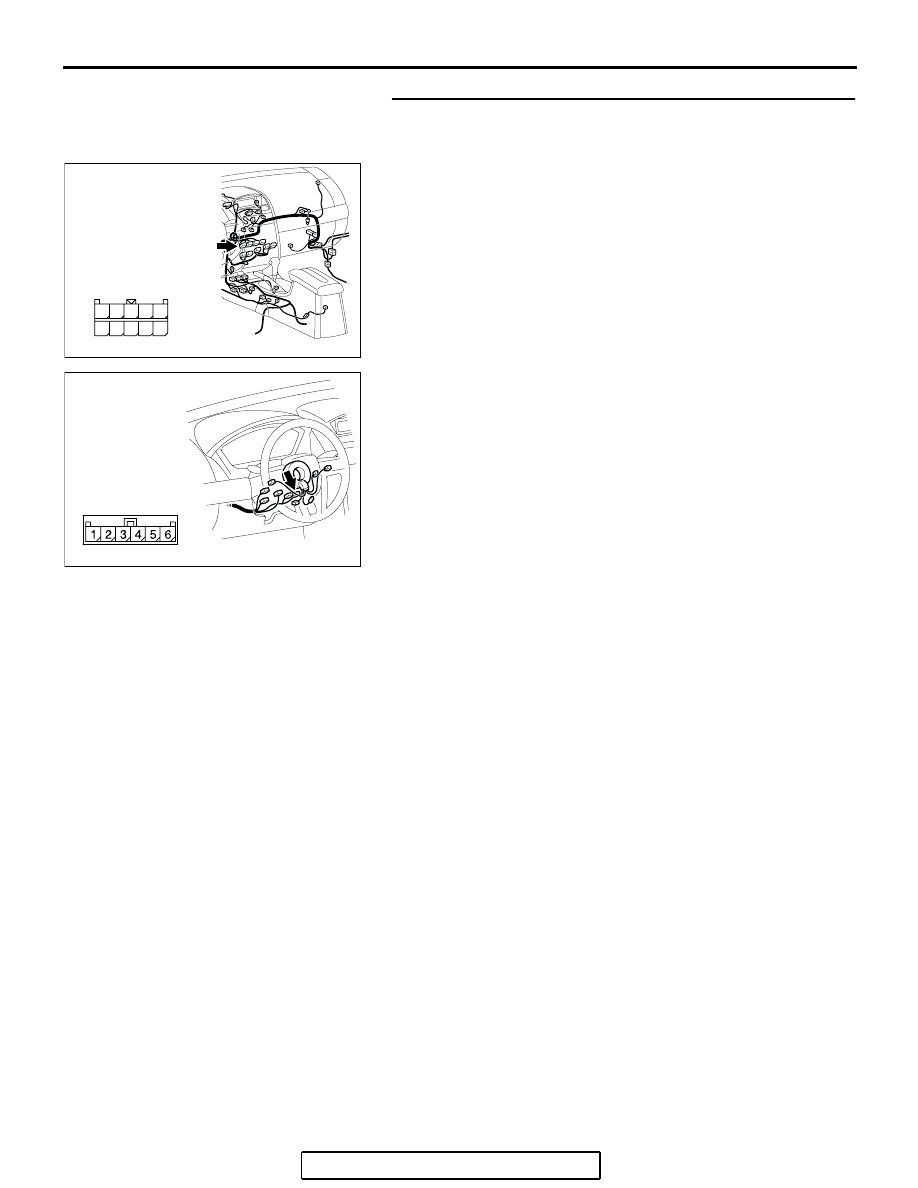
STEP 6. Check the wiring harness between radio, CD 
player and CD changer connector C-117 (terminal 45) and 
clock spring connector C-306 (terminal 3).
Q: Is the wiring harness between radio, CD player and CD 

changer connector C-117 (terminal 45) and clock spring 
connector C-306 (terminal 3) in good condition?
YES : 
Go to Step 7.
NO :  Repair the wiring harness. The remote controlled 

radio switch should work normally.

AC305233

HARNESS SIDE

CA

CONNECTOR: C-117

41

42

43

44

45

46

47

48

49

50

AC305235AH

CONNECTOR: C-306

RADIO WITH CD PLAYER

TSB Revision

CHASSIS ELECTRICAL

54A-145

STEP 7. Measure the resistance between the clock spring 
connector C-306 terminals.
(1) Disconnect the clock spring connector C-306.

(2) Measure the resistance between clock spring connector 

C-306 (clock spring side) terminals 2 and 3. Operate the 
right and left remote controlled radio switches, and check 
that the table below is satisfied.

NOTE: When checking the right remote controlled radio 
switch, do not operate the left remote controlled radio 
switch.

Q: Is the resistance between terminals 2 and 3 normal?

YES : This malfunction is intermittent. Refer to GROUP 00, 

How to Use Troubleshooting/Inspection Service 
Points-How to Cope with Intermittent Malfunction 

P.00-14

.

NO :  Go to Step 8.

SWITCH 
POSITION

MEASUREMENT VALUE (RH SIDE 
SWITCH)

No push

Approximately 24.0 k

Upper

Approximately 5.3 k

Center

Less than 2 ohms

Lower

Approximately 9.2 k

AC305235AH

CONNECTOR: C-306

AC210080

CONNECTOR C-306

AC

RADIO WITH CD PLAYER

TSB Revision

CHASSIS ELECTRICAL

54A-146

STEP 8. Measure the resistance at clock spring terminal.
(1) Remove the clock spring (Refer to GROUP 52B, Air Bag 

Module(s) and Clock Spring 

P.52B-369

).

(2) Measure the resistance at clock spring connectors C-303 

and C-306.

Q: Is the measured resistance 2 ohms or less?

YES : Go to Step 9.
NO :  Replace the clock spring.

CIRCUIT TO 
BE 
MEASURED

CONNECTOR 
(TERMINAL) 
TO BE 
CHECKED

SPECIFIED 
CONDITION

Power supply 
circuit

C-303 (terminal 
5) 

− C-306 

(terminal 2)

Less than 2 
ohms

Ground circuit

C-303 (terminal 
4) 

− C-306 

(terminal 3)

less than 2 
ohms

AC305236

CONNECTORS: C-303, C-306

C-306

C-303 (GR)

C-303

C-306

AC

1 2 3

5

4

6

4

1 2 3

5

AC211682

1 2 3

5

4

6

4

1 2 3

5

C-303

C-306

C-303

C-306

AB

POWER SUPPLY 
CIRCUIT CHECK

GROUND CIRCUIT
CHECK

RADIO WITH CD PLAYER

TSB Revision

CHASSIS ELECTRICAL

54A-147

STEP 9. Check the clock spring connector C-303 and 
remote controlled radio switch (RH) connector C-301 for 
loose, corroded or damaged terminals, or terminals 
pushed back in the connector.
Q: Are clock spring connector C-303 and remote controlled 

radio switch (RH) connector C-301 in good condition?
YES : 
Go to step 10.
NO :  Repair or replace the component(s). Refer to GROUP 

00E, Harness Connector Inspection 

P.00E-2

. The 

remote controlled radio switch should work normally.

STEP 10. Check the wiring harness between clock spring 
connector C-303 (terminals 4 and 5) and remote controlled 
radio switch (RH) connector C-301 (terminals 1 and 2).
Q: Is the wiring harness between clock spring connector 

C-303 (terminals 4 and 5) and remote controlled radio 
switch (RH) connector C-301 (terminals 1 and 2) in good 
condition?
YES : 
Go to Step 11.
NO :  Repair the wiring harness. The remote controlled 

radio switch should work normally.

AC305236

CONNECTORS: C-301, C-303

C-301 (B)

C-303 (GR)

C-301

C-303

HARNESS SIDE

AD

AC305236

CONNECTORS: C-301, C-303

C-301 (B)

C-303 (GR)

C-301

C-303

HARNESS SIDE

AD


Content   ..  1566  1567  1568  1569   ..