Mitsubishi Galant 9G. Manual - part 1566


  Index      Mitsubishi     Mitsubishi Galant 9G - service repair manual


Search            


Content   ..  1564  1565  1566  1567   ..


Mitsubishi Galant 9G. Manual - part 1566


RADIO WITH CD PLAYER

TSB Revision

CHASSIS ELECTRICAL

54A-136

CIRCUIT OPERATION

Power is supplied to the radio and CD player or 
radio, CD player and CD changer when the ignition 
switch is in the "ACC" position or "ON" position. 
When the ignition is switched on, the radio and CD 
player or radio, CD player and CD changer or radio, 
CD player and CD changer will return to the previous 
state when the ignition was switch off at the last time.

.

TECHNICAL DESCRIPTION (COMMENT)

The cause is probably a faulty radio and CD player or 
radio, CD player and CD changer power supply cir-
cuit .

.

TROUBLESHOOTING HINTS

• Damaged wiring harness or connector.

• Malfunction of the radio and CD player or radio, 

CD player and CD changer.

DIAGNOSIS

Required Special Tool:

• MB991223: Harness set

STEP 1. Check to see that the radio and CD player or radio, 
CD player and CD changer is energized when the power 
switch is turned ON.
(1) Turn the ignition switch to "ACC" position.
(2) Turn ON the radio and CD player or radio, CD player and 

CD changer power switch.

Q:  Is the radio and CD player or radio, CD player and CD 

changer energized when the power switch is turned 
ON?
YES : 
Go to Step 2.
NO :  Go to Step 5.

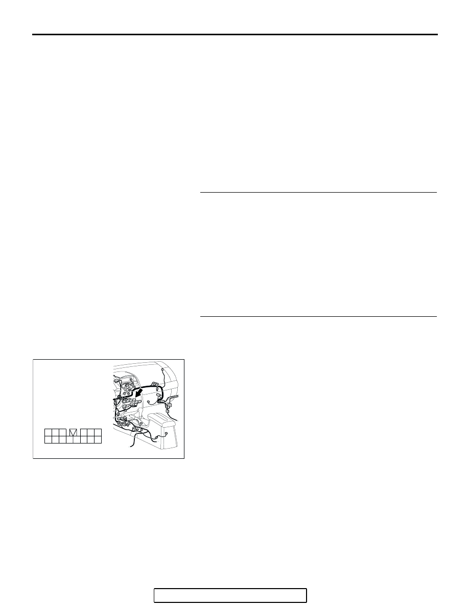
STEP 2. Check radio and CD player or radio, CD player and 
CD changer connector C-111 for loose, corroded or 
damaged terminals, or terminals pushed back in the 
connector.
Q: Are radio and CD player or radio, CD player and CD 

changer connector  C-111 in good condition?
YES : 
Go to Step 3.
NO :  Repair or replace the component(s). Refer to GROUP 

00E, Harness Connector Inspection 

P.00E-2

. If th

power switch is turned on, the radio and CD player or 
radio, CD player and CD changer should operate 
normally.

AC305233

HARNESS SIDE

3
9

4

12

14

6

13

5

1110

8

2

7

1

BY

CONNECTOR: C-111

RADIO WITH CD PLAYER

TSB Revision

CHASSIS ELECTRICAL

54A-137

STEP 3. Check the wiring harness between radio and CD 
player or radio, CD player and CD changer connector 
C-111 (terminal 10) and the ignition switch (ACC).

NOTE: Also check intermediate connector C-29 for loose, cor-
roded, or damaged terminals, or terminals pushed back in the 
connector. If intermediate connector C-29 is damaged, repair or 
replace it. Refer to GROUP 00E, Harness Connector Inspec-
tion 

P.00E-2

Q: Is the wiring harness between radio and CD player or 

radio, CD player and CD changer connector C-111 
(terminal 10) and ignition switch (ACC) in good 
condition?
YES : 
Go to Step 4.
NO :  Repair the wiring harness. If the power switch is 

turned on, the radio and CD player or radio, CD player 
and CD changer should operate normally.

STEP 4. Check the installation condition of the radio and 
CD player or radio, CD player and CD changer.
NOTE: The radio and CD player or radio, CD player and CD 
changer are grounded to the deck crossmember directly.
Q: Are the radio and CD player or radio, CD player and CD 

changer installed correctly?
YES : 
Repair or replace the radio and CD player or radio, 

CD player and CD changer. If the power switch is 
turned on, the radio and CD player or radio, CD player 
and CD changer should operate normally.

NO :  Install the radio and CD player or radio, CD player 

and CD changer properly. If the power switch is 
turned on, the radio and CD player or radio, CD player 
and CD changer should operate normally.

AC305233

HARNESS SIDE

3
9

4

12

14

6

13

5

1110

8

2

7

1

BY

CONNECTOR: C-111

AC305231AI

CONNECTOR: C-29

RADIO WITH CD PLAYER

TSB Revision

CHASSIS ELECTRICAL

54A-138

STEP 5. Measure at radio and CD player or radio, CD 
player and CD changer connector C-111 in order to check 
the battery circuit of power supply system to the radio and 
CD player or radio, CD player and CD changer (ignition 
switch ACC).
(1) Disconnect radio and CD player or radio, CD player and CD 

changer connector C-111, and measure at the wiring 
harness side.

(2) Turn the ignition switch to "ACC" position.

(3) Measure the voltage between terminal 10 and ground.

• The voltage should measure approximately 12 volts 

(battery positive voltage).

Q: Is the measured voltage approximately 12 volts (battery 

positive voltage)?
YES : 
Go to Step 8.
NO :  Go to Step 6.

STEP 6. Check radio and CD player or radio, CD player and 
CD changer connector C-111 for loose, corroded or 
damaged terminals, or terminals pushed back in the 
connector.
Q: Are radio and CD player or radio, CD player and CD 

changer connector  C-111 in good condition?
YES : 
Go to Step 7.
NO :  Repair or replace the damaged component(s). Refer 

to GROUP 00E, Harness Connector Inspection 

P.00E-2

. If the power switch is turned on, the radio 

and CD player or radio, CD player and CD changer 
should operate normally.

AC305233

HARNESS SIDE

3
9

4

12

14

6

13

5

1110

8

2

7

1

BY

CONNECTOR: C-111

AC209365

3
9

4

12

14

6

13

5

1110

8

2

7

1

CONNECTOR C-111 
(HARNESS SIDE)

HV

AC305233

HARNESS SIDE

3
9

4

12

14

6

13

5

1110

8

2

7

1

BY

CONNECTOR: C-111

RADIO WITH CD PLAYER

TSB Revision

CHASSIS ELECTRICAL

54A-139

STEP 7. Check the wiring harness between radio and CD 
player or radio, CD player and CD changer connector 
C-111 (terminal 10) and ignition switch (ACC).

NOTE: Also check intermediate connector C-29 for loose, cor-
roded, or damaged terminals, or terminals pushed back in the 
connector. If intermediate connector C-29 is damaged, repair or 
replace the connector as described in GROUP 00E, Harness 
Connector Inspection 

P.00E-2

Q: Is the wiring harness between radio and CD player or 

radio, CD player and CD changer connector C-111 
(terminal 10) and ignition switch (ACC) in good 
condition?
YES : 
There is no action to be taken.
NO :  Repair the wiring harness. If the power switch is 

turned on, the radio and CD player or radio, CD player 
and CD changer should operate normally.

STEP 8. Check the installation condition of the radio and 
CD player or radio, CD player and CD changer.
NOTE: The radio and CD player or radio, CD player and CD 
changer are grounded to the deck crossmember directly.
Q: Are the radio and CD player or radio, CD player and CD 

changer installed correctly?
YES : 
Replace the radio and CD player or radio, CD player 

and CD changer. If the power switch is turned on, the 
radio and CD player or radio, CD player and CD 
changer should operate normally.

NO :  Install the radio and CD player or radio, CD player 

and CD changer properly. If the power switch is 
turned on, the radio and CD player or radio, CD player 
and CD changer should operate normally.

AC305233

HARNESS SIDE

3
9

4

12

14

6

13

5

1110

8

2

7

1

BY

CONNECTOR: C-111

AC305231AI

CONNECTOR: C-29


Content   ..  1564  1565  1566  1567   ..