Content .. 1567 1568 1569 1570 ..
Mitsubishi Galant 9G. Manual - part 1569
RADIO WITH CD PLAYER
TSB Revision
CHASSIS ELECTRICAL
54A-148
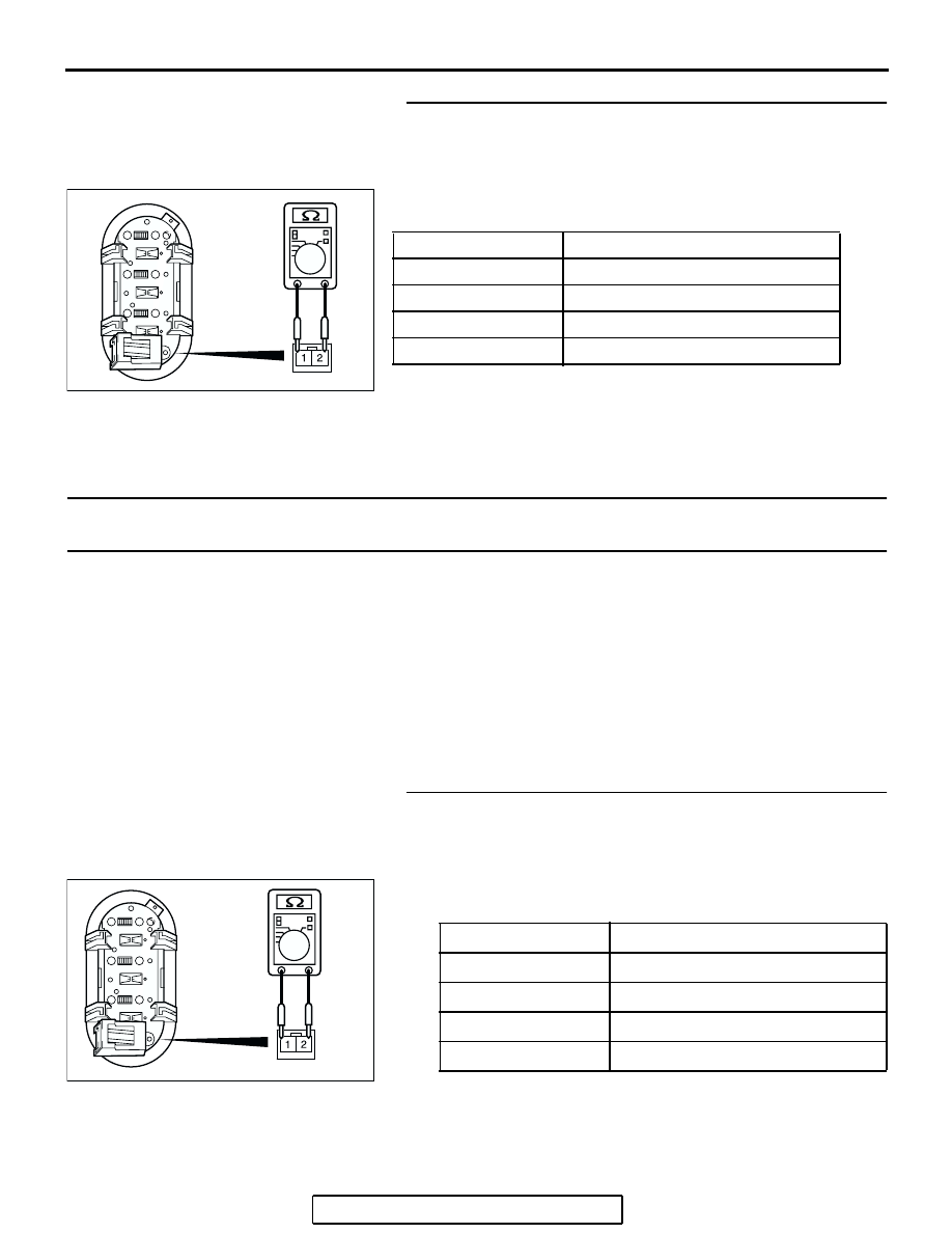
STEP 11. Measure the resistance at remote controlled
radio switch (RH).
(1) Remove the airbag module assembly (Refer to GROUP
52B, Air Bag Module(s) and Clock Spring
(2) Measure the resistance by operating the remote controlled
radio switch (RH) in each position.
Q: Are the resistance at the right remote controlled radio
switch normal?
YES : Replace the radio, CD player and CD changer.
NO : Replace the remote controlled radio switch (RH).
INSPECTION PROCEDURE 3: The system does not recognize the remote controlled radio switch (RH)
only. <Vehicles with Audio Amplifier>
.
CIRCUIT OPERATION
Refer to Inspection Procedure 2
.
TECHNICAL DESCRIPTION (COMMENT)
Refer to Inspection Procedure 2
.
TROUBLESHOOTING HINTS
Refer to Inspection Procedure 2
DIAGNOSIS
Required Special Tool:
• MB991223: Harness set
STEP 1. Measure the resistance at remote controlled radio
switch (RH).
(1) Remove the airbag module assembly (Refer to GROUP
52B, Air Bag Module(s) and Clock Spring
(2) Measure the resistance by operating the remote controlled
radio switch (RH) in each position.
Q: Are the resistance at the right remote controlled radio
switch normal?
YES : Go to Step 2.
NO : Replace the remote controlled radio switch (RH).
SWITCH POSITION MEASUREMENT VALUE
No push
Approximately 24.0 k
Ω
Upper
Approximately 6.8 k
Ω
Center
Less than 2 ohms
Lower
Approximately 15.0 k
Ω
AC211680AB
SWITCH POSITION MEASUREMENT VALUE
No push
Approximately 24.0 k
Ω
Upper
Approximately 6.8 k
Ω
Center
Less than 2 ohms
Lower
Approximately 15.0 k
Ω
AC211691AB