Content .. 1486 1487 1488 1489 ..
Mitsubishi Galant 9G. Manual - part 1488
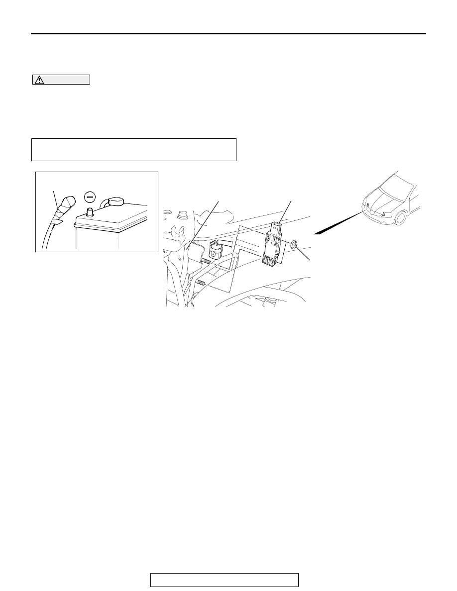
FRONT IMPACT SENSORS
TSB Revision
SUPPLEMENTAL RESTRAINT SYSTEM (SRS)
52B-362
FRONT IMPACT SENSORS
REMOVAL AND INSTALLATION
M1524001500300
WARNING
•
Never repair or disassemble the front impact sensor. If faulty, replace it.
•
Handle the front impact sensors very carefully, taking care not to drop them. They must
be replaced if they are dropped.
•
Replace the sensors with new ones after the air bag has deployed.
NOTE: The figure indicates the right front impact
sensor. The left impact sensor is symmetrical to this.
Pre-removal Operation
• Turn the ignition key to the "LOCK" (OFF) position.
AC307984
AB
1
7.5 ± 2.5 N·m
67 ± 22 in-lb
2
RADIATOR SUPPORT PANEL
REMOVAL STEPS
<<A>>
1.
NEGATIVE (-) BATTERY CABLE
CONNECTION
•
AIR DUCT (REFER TO GROUP
15, AIR CLEANER )
2.
FRONT IMPACT SENSOR
INSTALLATION STEPS
>>A<<
•
PRE-INSTALLATION
INSPECTION
>>B<<
2.
FRONT IMPACT SENSOR
•
AIR DUCT (REFER TO GROUP
15, AIR CLEANER )
1.
NEGATIVE (-) BATTERY CABLE
CONNECTION
>>C<<
•
POST-INSTALLATION
INSPECTION