Content .. 1487 1488 1489 1490 ..
Mitsubishi Galant 9G. Manual - part 1489
SRS CONTROL UNIT (SRS-ECU)
TSB Revision
SUPPLEMENTAL RESTRAINT SYSTEM (SRS)
52B-366
REMOVAL SERVICE POINTS
.
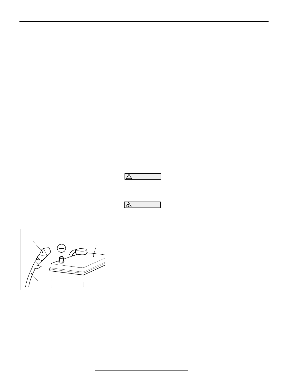
<<A>> NEGATIVE (
−) BATTERY CABLE DISCON-
NECTION
DANGER
Wait at least 60 seconds after disconnecting the bat-
tery cable before doing any further work (Refer to
).
WARNING
Battery posts, terminals and related accessories con-
tain lead and lead compounds. WASH HANDS AFTER
HANDLING.
Disconnect the negative battery cable from the battery and tape
the terminal to prevent accidental connection and deployment.
.
<<B>> SRS-ECU REMOVAL
Remove the SRS-ECU with 9.5 (3/8inch) sq. slide head handle
and 9.5 sq. (3/8inch) socket wrench.
REMOVAL STEPS
<<A>>
1.
NEGATIVE (
−) BATTERY CABLE
CONNECTION
•
FLOOR CONSOLE ASSEMBLY
(REFER TO GROUP 52A, FLOOR
CONSOLE ASSEMBLY
•
FRONT SEAT ASSEMBLY
(REFER TO GROUP 52A, FRONT
SEAT ASSEMBLY
•
FRONT SCUFF PLATE, COWL
SIDE TRIM (REFER TO GROUP
52A, TRIMS
•
FLOOR CARPET
•
REAR HEATER DUCT A, B
(REFER TO GROUP 55A,
DUCTS )
<<B>>
2.
SRS-ECU
3.
SRS-ECU BRACKET
INSTALLATION STEPS
3.
SRS-ECU BRACKET
>>A<<
2.
SRS-ECU
•
REAR HEATER DUCT A, B
(REFER TO GROUP 55A,
DUCTS )
•
FLOOR CARPET
•
FRONT SCUFF PLATE, COWL
SIDE TRIM (REFER TO GROUP
52A, TRIMS
•
FRONT SEAT ASSEMBLY
(REFER TO GROUP 52A, FRONT
SEAT ASSEMBLY
•
FLOOR CONSOLE ASSEMBLY
(REFER TO GROUP 52A, FLOOR
CONSOLE ASSEMBLY
1.
NEGATIVE (
−) BATTERY CABLE
CONNECTION
>>B<<
•
POST-INSTALLATION
INSPECTION
ACX00583
INSULATING TAPE
BATTERY
BATTERY CABLE (–)
AC