Content .. 1256 1257 1258 1259 ..
Mitsubishi Galant 9G. Manual - part 1258
DIAGNOSIS
TSB Revision
CONTROLLER AREA NETWORK (CAN)
54C-136
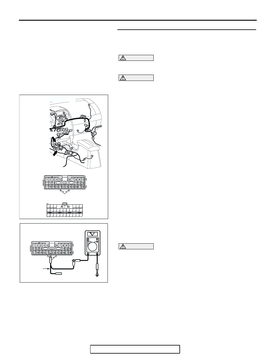
STEP 19. Check the CAN_ H line (communication line only)
between the SRS-ECU connector and the intermediate
connector for a short circuit. Measure the voltage at
intermediate connector C-22.
CAUTION
A digital multimeter should be used. For details refer to
.
CAUTION
The test wiring harness should be used. For details refer to
.
(1) Disconnect intermediate connector C-22 and SRS-ECU
connector C-121, and measure the voltage at the male side
of intermediate connector C-22 (at floor wiring harness
side).
(2) Turn the ignition switch to the "ON" position.
(3) Measure the voltage between intermediate connector
terminal 22 and body ground.
OK: 1.0 V or less
CAUTION
Strictly observe the specified wiring harness repair proce-
dure. For details refer to
Q: Does the voltage measure 1.0 V or less?
YES : If the voltage measures 1.0 V or less, diagnose CAN
bus lines thoroughly by referring to
NO : If the voltage measures more than 1.0 V, repair the
wiring harness between intermediate connector C-22
and SRS-ECU connector.
AC305234AC
CONNECTORS: C-22, C-121
C-121 HARNESS SIDE
C-121 (Y)
C-22 (Y)
C-22
48
21
22
23
24
25
26
27
28
29
30
31
32
33
34
35
36
37
38
39
40
41
42
43
44
45
46
47
AC209365
AC209365FT
MAIL SIDE: C-22
TEST
HARNESS