Mitsubishi Galant 9G. Manual - part 1257


  Index      Mitsubishi     Mitsubishi Galant 9G - service repair manual


Search            


Content   ..  1255  1256  1257  1258   ..


Mitsubishi Galant 9G. Manual - part 1257


DIAGNOSIS

TSB Revision

CONTROLLER AREA NETWORK (CAN)

54C-132

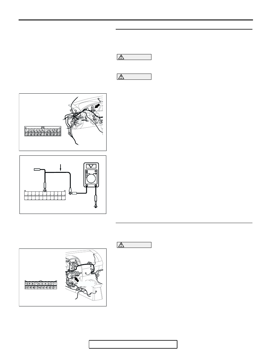
STEP 12. Check the CAN_H line (communication line 
including the A/C-ECU) between joint connector (3) and 
the A/C-ECU connector for a short to the power supply. 
Measure the voltage at joint connector (3) C-02.

CAUTION

A digital multimeter should be used. For details refer to 

P.54C-4

.

CAUTION

The test wiring harness should be used. For details refer to 

P.54C-4

.

(1) Disconnect joint connector (3) C-02, and measure the 

voltage at the wiring harness side of joint connector (3) 
C-02.

(2) Turn the ignition switch to the "ON" position.

(3) Measure the voltage between joint connector (3) terminal 6 

and body ground.

OK: 4.0 V or less

Q: Does the voltage measure 4.0 V or less?

YES : If the voltage measures 4.0 V or less, go to Step 15.
NO :  If the voltage measures more than 4.0 V, go to Step 

13.

STEP 13. Check A/C-ECU connector C-15 for loose, 
corroded or damaged terminals, or terminals pushed back 
in the connector.

CAUTION

The strand end of the twisted wire should be within 10 cm 
(4 inches) from the connector. For details refer to 

P.54C-4

.

Q: Is A/C-ECU connector C-15 in good condition?

YES : Go to Step 14.
NO :  Repair the damaged parts.

AC305231AP

CONNECTOR: C-02

AC209365

11

22

10

21

9

20

8

19

7

18

6

17

5

16

4

15

3

14

2

13

1

12

AC209365

AC209365

HARNESS SIDE: C-02

FS

TEST HARNESS

AC305233 AH

CONNECTOR: C-15

HARNESS SIDE

C-15 (B)

DIAGNOSIS

TSB Revision

CONTROLLER AREA NETWORK (CAN)

54C-133

STEP 14. Check the CAN_H line (communication line only) 
between joint connector (3) and A/C-ECU connector for a 
short to the power supply. Measure the voltage at joint 
connector (3) C-02.

CAUTION

A digital multimeter should be used. For details refer to 

P.54C-4

.

CAUTION

The test wiring harness should be used. For details refer to 

P.54C-4

.

(1) Disconnect joint connector (3) C-02 and A/C-ECU 

connector C-15, and measure the voltage at the wiring 
harness side of joint connector (3) C-02.

(2) Turn the ignition switch to the "ON" position.

(3) Measure the voltage between joint connector (3) terminal 6 

and body ground.

OK: 1.0 V or less

CAUTION

Strictly observe the specified wiring harness repair proce-
dure. For details refer to 

P.54C-5

.

Q: Does the voltage measure 1.0 V or less?

YES : If the voltage measures 1.0 V or less, diagnose CAN 

bus lines thoroughly by referring to 

P.54C-520

.

NO :  If the voltage measures more than 1.0 V, repair the 

wiring harness between joint connector (3) and the 
A/C-ECU connector.

AC305231AP

CONNECTOR: C-02

AC305233 AH

CONNECTOR: C-15

HARNESS SIDE

C-15 (B)

AC209365

11

22

10

21

9

20

8

19

7

18

6

17

5

16

4

15

3

14

2

13

1

12

AC209365

AC209365

HARNESS SIDE: C-02

FS

TEST HARNESS

DIAGNOSIS

TSB Revision

CONTROLLER AREA NETWORK (CAN)

54C-134

STEP 15. Check the CAN_H line (communication line 
including the SRS-ECU) between joint connector (3) and 
the SRS-ECU connector for short to the power supply. 
Measure the voltage at joint connector (3) C-02.

CAUTION

A digital multimeter should be used. For details refer to 

P.54C-4

.

CAUTION

The test wiring harness should be used. For details refer to 

P.54C-4

.

(1) Disconnect joint connector (3) C-02, and measure the 

voltage at the wiring harness side of joint connector (3) 
C-02.

(2) Turn the ignition switch to the "ON" position.

(3) Measure the voltage between joint connector (3) terminal 3 

and body ground.

OK: 4.0 V or less

Q: Does the voltage measure 4.0 V or less?

YES : If the voltage measures 4.0 V or less, go to Step 21.
NO :  If the voltage measures more than 4.0 V, go to Step 

16.

STEP 16. Check intermediate connector C-22 for loose, 
corroded or damaged terminals, or terminals pushed back 
in the connector.

CAUTION

The strand end of the twisted wire should be within 10 cm 
(4 inches) from the connector. For details refer to 

P.54C-4

.

Q: Is intermediate connector C-22 in good condition?

YES : Go to Step 17.
NO :  Repair the damaged parts.

AC305231AP

CONNECTOR: C-02

AC209365

11

22

10

21

9

20

8

19

7

18

6

17

5

16

4

15

3

14

2

13

1

12

AC209365FU

HARNESS SIDE: C-02

TEST 
HARNESS

AC305233 AI

CONNECTOR: C-22

C-22 (Y)

DIAGNOSIS

TSB Revision

CONTROLLER AREA NETWORK (CAN)

54C-135

STEP 17. Check the CAN_H-side bus line (communication 
line including ECUs) of the floor wiring harness for short 
to the power supply. Measure the voltage at intermediate 
connector C-22.

CAUTION

A digital multimeter should be used. For details refer to 

P.54C-4

.

CAUTION

The test wiring harness should be used. For details refer to 

P.54C-4

.

(1) Disconnect intermediate connector C-22, and measure the 

voltage at the male side (at floor wiring harness side).

(2) Turn the ignition switch to the "ON" position.

(3) Measure the voltage between intermediate connector 

terminal 22 and body ground.

OK: 4.0 V or less

Q: Does the voltage measure 4.0 V or less?

YES : If the voltage measures 4.0 V or less, go to Step 20  .
NO :  If the voltage measures more than 4.0 V, go to Step 

18.

STEP 18. Check SRS-ECU connector C-121 for loose, 
corroded or damaged terminals, or terminals pushed back 
in the connector.

CAUTION

The strand end of the twisted wire should be within 10 cm 
(4 inches) from the connector. For details refer to 

P.54C-4

.

Q: Is SRS-ECU connector C-121 in good condition?

YES : Go to Step 19.
NO :  Repair the damaged parts.

AC305233 AI

CONNECTOR: C-22

C-22 (Y)

AC209365

AC209365FT

MAIL SIDE: C-22

TEST 
HARNESS

AC305233 AJ

CONNECTOR: C-121

HARNESS SIDE

C-121 (Y)

48

21

22

23

24

25

26

27

28

29

30

31

32

33

34

35

36

37

38

39

40

41

42

43

44

45

46

47


Content   ..  1255  1256  1257  1258   ..