Mitsubishi Galant 9G. Manual - part 1010


  Index      Mitsubishi     Mitsubishi Galant 9G - service repair manual


Search            


Content   ..  1008  1009  1010  1011   ..


Mitsubishi Galant 9G. Manual - part 1010


MULTIPORT FUEL INJECTION (MFI) DIAGNOSIS

TSB Revision

MULTIPORT FUEL INJECTION (MFI) <3.8L ENGINE>

13B-340

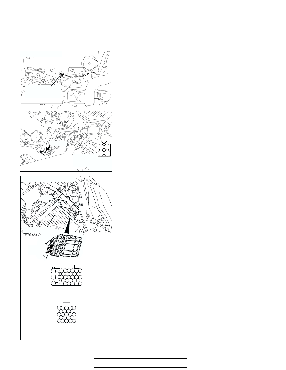
STEP 3. Check harness connector B-25 at left bank heated 
oxygen sensor (front) and harness connector B-21, B-22 at 
PCM for  damage.

Q: Is the harness connector in good condition?

YES : Replace the PCM. Then go to Step 4.
NO :  Repair or replace it. Refer to GROUP 00E, Harness 

Connector Inspection 

P.00E-2

. Then go to Step 4.

AK303071

1

2

3

4

LEFT BANK
HEATED OXYGEN
SENSOR (FRONT)

CONNECTOR: B-25

B-25 (B)

AB

HARNESS
CONNECTOR:
COMPONENT SIDE

AK303052

55

56

54 53 52 51

57

62 61 60 59 58

63

69 68 67 66 65 64

70

75 74 73 72 71

76

82 81 80 79 78 77

83

104

96

94

95

93 92 91

99 98 97

103 102 101 100

108 107 106 105

113 112 111 110 109

CONNECTORS: B-21, B-22

AB

B-21 HARNESS CONNECTOR: 
COMPONENT SIDE

B-22 HARNESS CONNECTOR: 
COMPONENT SIDE

PCM

AIR CLEANER

B-22 (B)

B-21 (B)

MULTIPORT FUEL INJECTION (MFI) DIAGNOSIS

TSB Revision

MULTIPORT FUEL INJECTION (MFI) <3.8L ENGINE>

13B-341

STEP 4. Test the OBD-II drive cycle.

(1) Carry out a test drive with the drive cycle pattern. Refer to 

Diagnostic Function 

− OBD-II Drive Cycle − Procedure 4 − 

Heated Oxygen Sensor Monitor 

P.13B-6

.

(2) Check the diagnostic trouble code (DTC).
Q: Is DTC P0153 set?

YES : Retry the troubleshooting.
NO :  The inspection is complete.

DTC P0154: Heated Oxygen Sensor Circuit No Activity Detected (bank 2, sensor 1)

CAUTION

If DTC P0154 has been set, TCL related DTC 
U1120 is also set. After P0154 has been diag-
nosed, don't forget to erase DTC U1120.

.

Heated Oxygen Sensor Circuit No Activity 
Detected (bank 2, sensor 1) Circuit

• Refer to, DTC P0150 − Left Bank Heated Oxygen 

Sensor (Front) Circuit 

P.13B-305

.

• Refer to, DTC P0202

P.13B-493

P0204

P.13B-516

, P0206

P.13B-539


− Injector 

Circuit.

.

CIRCUIT OPERATION

• Refer to, DTC P0152 − Left Bank Heated Oxygen 

Sensor (Front) Circuit 

P.13B-330

.

• Refer to, DTC P0202

P.13B-493

P0204

P.13B-516

, P0206

P.13B-539


− Injector 

Circuit.

.

TECHNICAL DESCRIPTION

• The PCM effects air/fuel ratio feedback control in 

accordance with the signals from the left bank 
heater oxygen sensor (front).

• If the left bank heated oxygen sensor (front) has 

deteriorated, corrections will be made by the 
heated oxygen sensor (rear).

• DTC P0154 becomes stored in memory if a fail-

ure is detected in the above air/fuel ratio feed-
back control system.

.

DESCRIPTIONS OF MONITOR METHODS

Left bank heated oxygen sensor (front) output volt-

age does not cross 0.5 volt within specified 
period.

.

MONITOR EXECUTION

Continuous

.

MONITOR EXECUTION CONDITIONS 
(Other monitor and Sensor)

Other Monitor (There is no temporary DTC stored 

in memory for the item monitored below)

• Misfire monitor

Sensor (The sensor below is determined to be 

normal)

• Mass airflow sensor

• Engine coolant temperature sensor

• Intake air temperature sensor

• Barometric pressure sensor

• Throttle position sensor

.

MULTIPORT FUEL INJECTION (MFI) DIAGNOSIS

TSB Revision

MULTIPORT FUEL INJECTION (MFI) <3.8L ENGINE>

13B-342

DTC SET CONDITIONS

Logic Flow Chart

.

Check Conditions

• 20 seconds or more have passed since the 

engine starting sequence was completed.

• Engine coolant temperature is higher than 50°C 

(122

° F).

• Engine speed is higher than 1,200 r/min.

• Volumetric efficiency is higher than 30 percent.

• Throttle position sensor output voltage is lower 

than 4 volts.

• Except while fuel is being shut off.

• Monitoring time: 30 seconds.

Judgment Criteria

• Left bank heated oxygen sensor (front) output 

voltage does not get across 0.5 volt within about 
30 seconds.

.

OBD-II DRIVE CYCLE PATTERN

Refer to Diagnostic Function 

− OBD-II Drive Cycle − 

Procedure 6 

− Other Monitor 

P.13B-6

.

.

HEATED OXYGEN SENSOR (FRONT) 

OUTPUT VOLTAGE CROSSES 0.5V?

START

END

NO

NO

NO

YES

Yes

YES

MALFUNCTION

GOOD

30secs HAVE PASSED?

MONITORING

CONDITIONS

AK203999

MULTIPORT FUEL INJECTION (MFI) DIAGNOSIS

TSB Revision

MULTIPORT FUEL INJECTION (MFI) <3.8L ENGINE>

13B-343

TROUBLESHOOTING HINTS (The most 
likely causes for this code to be set are: )

• Left bank heated oxygen sensor (front) deterio-

rated.

• Harness damage in left bank heated oxygen sen-

sor (front) output line.

• Left bank heated oxygen sensor (rear) deterio-

rated.
NOTE: When the left bank heated oxygen sensor 
(front) begins to deteriorate, the heated oxygen 
sensor output voltage will deviate from the volt-
age when the sensor was new (normally 0.5 volt 
at stoichiometric ratio). This deviation will be cor-
rected by the left bank heated oxygen sensor 
(rear).

If the left bank heated oxygen sensor (rear) 
responds poorly because it has deteriorated, it 
will improperly correct the left bank heated oxy-
gen sensor (front). Thus, even when closed loop 
control is being effected, the fluctuation of the left 
bank heated oxygen sensor (front) output voltage 
decreases, without intersecting with 0.5 volt. As a 
result, there is a possibility of DTC P0154 becom-
ing registered.

• Open circuit in left bank injector.

• Harness damage in left bank injector circuit.

• Connector damage.

• PCM failed.

• Exhaust leak.

• Air drawn in from gaps in gasket, seals, etc.

• Incorrect fuel pressure.

DIAGNOSIS

Required Special Tools:

• MB991958: Scan Tool (MUT-III Sub Assembly)

• MB991824: V.C.I.

• MB991827: USB Cable

• MB991910: Main Harness A

• MD998464: Test Harness

STEP 1. Using scan tool MB991958, check data list item 59: 
Heated Oxygen Sensor Bank 2, Sensor 2 (left rear).

CAUTION

To prevent damage to scan tool MB991958, always turn the 
ignition switch to the "LOCK" (OFF) position before con-
necting or disconnecting scan tool MB991958.
(1) Connect scan tool MB991958 to the data link connector.
(2) Start the engine and run at idle.

(3) Set scan tool MB991958 to the data reading mode for item 

59, Heated Oxygen Sensor Bank 2, Sensor 2 (left rear).

• Warming up the engine. When the engine is revved, the 

output voltage should repeat 0 volt and 0.6 to 1.0 volt 
alternately.

(4) Turn the ignition switch to the "LOCK" (OFF) position.
Q: Is the sensor operating properly?

YES : Go to Step 2. 
NO :  Refer to, DTC P0156 

− Heated Oxygen Sensor Circuit 

(bank 2, sensor 2) 

P.13B-365

, DTC P0157 

− Heated 

Oxygen Sensor Circuit Low Voltage (bank 2, sensor 
2) 

P.13B-382

, DTC P0158-Heated Oxygen Sensor 

Circuit High Voltage (bank 2, sensor 2) 

P.13B-389

DTC P0159 

− Heated Oxygen Sensor Circuit Slow 

Response (bank 2, sensor 2) 

P.13B-394

AC305412

AB

MB991910

DATA LINK

CONNECTOR

MB991824

MB991827


Content   ..  1008  1009  1010  1011   ..