Mitsubishi Galant 9G. Manual - part 1008


  Index      Mitsubishi     Mitsubishi Galant 9G - service repair manual


Search            


Content   ..  1006  1007  1008  1009   ..


Mitsubishi Galant 9G. Manual - part 1008


MULTIPORT FUEL INJECTION (MFI) DIAGNOSIS

TSB Revision

MULTIPORT FUEL INJECTION (MFI) <3.8L ENGINE>

13B-332

DTC SET CONDITIONS

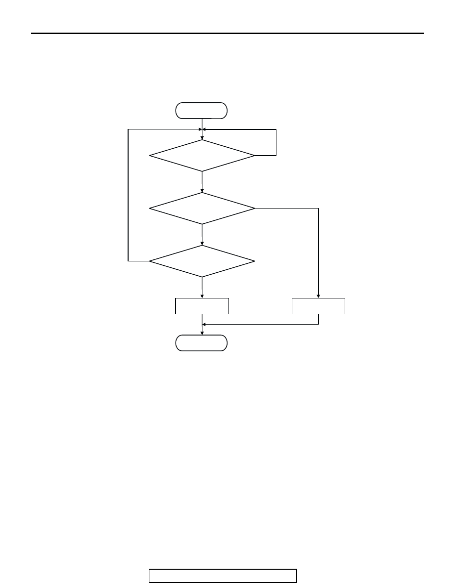
Logic Flow Chart

.

Check Conditions

• 2 seconds or more have passed since the engine 

starting sequence was completed.

Judgment Criteria

• Left bank heated oxygen sensor (front) output 

voltage has continued to be 1.2 volts or higher for 
2 seconds.

.

OBD-II DRIVE CYCLE PATTERN

Refer to Diagnostic Function 

− OBD-II Drive Cycle − 

Procedure 6 

− Other Monitor 

P.13B-6

.

.

TROUBLESHOOTING HINTS (The most 
likely causes for this code to be set are: )

• Short circuit in left bank heated oxygen sensor 

(front) output line.

• Connector damage.

• PCM failed.

START

END

NO

NO

YES

YES

MALFUNCTION

GOOD

2secs HAVE PASSED?

OUTPUT VOLTAGE > 1.2V

NO

YES

MONITORING

CONDITIONS

AK302396

MULTIPORT FUEL INJECTION (MFI) DIAGNOSIS

TSB Revision

MULTIPORT FUEL INJECTION (MFI) <3.8L ENGINE>

13B-333

DIAGNOSIS

STEP 1. Check harness connector B-25 at left bank heated 
oxygen sensor (front) and harness connector B-22 at PCM 
for damage.

Q: Is the harness connector in good condition?

YES : Go to Step 2.
NO :  Repair or replace it. Refer to GROUP 00E, Harness 

Connector Inspection 

P.00E-2

. Then go to Step 3.

AK303071

1

2

3

4

LEFT BANK
HEATED OXYGEN
SENSOR (FRONT)

CONNECTOR: B-25

B-25 (B)

AB

HARNESS
CONNECTOR:
COMPONENT SIDE

AK303016

104

96

94

95

93 92 91

99 98 97

103 102 101 100

108 107 106 105

113 112 111 110 109

CONNECTOR: B-22

B-22 (B)

PCM

AB

HARNESS CONNECTOR: 
COMPONENT SIDE

AIR CLEANER

MULTIPORT FUEL INJECTION (MFI) DIAGNOSIS

TSB Revision

MULTIPORT FUEL INJECTION (MFI) <3.8L ENGINE>

13B-334

STEP 2. Check for short circuit to power supply between 
left bank heated oxygen sensor (front) connector B-25 
(terminal No. 4) and PCM connector B-22 (terminal No. 91).

Q: Is the harness wire in good condition?

YES : Replace the PCM. Then go to Step 3.
NO :  Repair it. Then go to Step 3.

AK303071

1

2

3

4

LEFT BANK
HEATED OXYGEN
SENSOR (FRONT)

CONNECTOR: B-25

B-25 (B)

AB

HARNESS
CONNECTOR:
COMPONENT SIDE

AK303016

104

96

94

95

93 92 91

99 98 97

103 102 101 100

108 107 106 105

113 112 111 110 109

CONNECTOR: B-22

B-22 (B)

PCM

AB

HARNESS CONNECTOR: 
COMPONENT SIDE

AIR CLEANER

MULTIPORT FUEL INJECTION (MFI) DIAGNOSIS

TSB Revision

MULTIPORT FUEL INJECTION (MFI) <3.8L ENGINE>

13B-335

STEP 3. Test the OBD-II drive cycle.

(1) Carry out a test drive with the drive cycle pattern. Refer to 

Diagnostic Function 

− OBD-II Drive Cycle − Procedure 6 − 

Other Monitor 

P.13B-6

.

(2) Check the diagnostic trouble code (DTC).
Q: Is DTC P0152 set?

YES : Retry the troubleshooting.
NO :  The inspection is complete.

DTC P0153: Heated Oxygen Sensor Circuit Slow Response (bank 2, sensor 1)

BLA

CK

BLA

CK

TO PCM

FROM MFI RELAY

WHITE

AK400903

69

91

4

3

1

LEFT BANK
HEATED OXYGEN
SENSOR (FRONT)

POWERTRAIN CONTROL
MODULE (PCM)

2

B-25

MU802605

B-22

Left Bank Heated Oxygen Sensor (front) Circuit

B-21

1

2

3

4

52

51

53 54 55 56

57

58 59 60 61 62

63

64 65 66 67 68 69

70

71 72 73 74 75

76

77 78 79 80 81 82

83

100

99

92

91

93 94 95

96 97 98

101 102 103 104

105 106 107 108

109 110 111 112 113


Content   ..  1006  1007  1008  1009   ..