Content .. 1007 1008 1009 1010 ..
Mitsubishi Galant 9G. Manual - part 1009
MULTIPORT FUEL INJECTION (MFI) DIAGNOSIS
TSB Revision
MULTIPORT FUEL INJECTION (MFI) <3.8L ENGINE>
13B-336
.
CIRCUIT OPERATION
• A voltage corresponding to the oxygen concen-
tration in the exhaust gas is sent to the PCM (ter-
minal No. 91) from the output terminal (terminal
No. 4) of the left bank heated oxygen sensor
(front).
• Terminal No. 2 of the left bank heated oxygen
sensor (front) is grounded with PCM (terminal
No. 69).
.
TECHNICAL DESCRIPTION
• The left bank heated oxygen sensor (front)
detects the concentration of oxygen in the
exhaust gas; it converts those data to voltage,
and inputs the resulting signals to the PCM.
• When the left bank heated oxygen sensor (front)
begins to deteriorate, the left bank heated oxygen
sensor signal response becomes poor.
• The PCM forcibly varies the air/fuel mixture to
make it leaner and richer, and checks the
response speed of the left bank heated oxygen
sensor (front). In addition, the PCM also checks
for an open circuit in the left bank heated oxygen
sensor (front) output line.
.
DESCRIPTIONS OF MONITOR METHODS
Left bank heated oxygen sensor (front) rich/lean
switching frequency is under specified value.
.
MONITOR EXECUTION
Continuous
.
MONITOR EXECUTION CONDITIONS
(Other monitor and Sensor)
Other Monitor (There is no temporary DTC stored
in memory for the item monitored below)
• Heated oxygen sensor heater (front) monitor
• Misfire monitor
• Fuel system monitor
Sensor (The sensor below is determined to be
normal)
• Mass airflow sensor
• Engine coolant temperature sensor
• Intake air temperature sensor
• Barometric pressure sensor
• Throttle position sensor
• Accelerator pedal position sensor
.
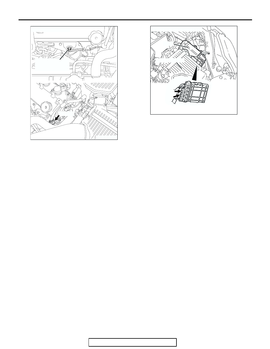
AK303070
LEFT BANK
HEATED OXYGEN
SENSOR (FRONT)
CONNECTOR: B-25
B-25 (B)
AB
AK303013
CONNECTORS: B-21, B-22
PCM
AB
AIR CLEANER
B-22 (B)
B-21 (B)