Mitsubishi Galant 9G. Manual - part 19


  Index      Mitsubishi     Mitsubishi Galant 9G - service repair manual


Search            


Content   ..  17  18  19  20   ..


Mitsubishi Galant 9G. Manual - part 19


SYMPTOM PROCEDURES

TSB Revision

SIMPLIFIED WIRING SYSTEM (SWS)

54B-72

.

CIRCUIT OPERATION

• The power supply to the column switch is pro-

vided by the battery and the ignition switch (IG1).

• If the power supply system from the battery is 

defective, the system operates by the power sup-
ply from the ignition switch (IG1).

.

TECHNICAL DESCRIPTION (COMMENT)

The power supply circuit to the column switch (col-
umn-ECU) may be defective. If the battery power 
supply circuit (terminal 1 of the column switch) to the 
ECU is damaged, also check the power supply circuit 
from the ignition switch (IG1) (terminal 9 of the col-
umn switch), and repair if necessary.

.

TROUBLESHOOTING HINTS

• The wiring harness or connectors may have 

loose, corroded, or damaged terminals, or termi-
nals pushed back in the connector

• The column switch may be defective

• The ETACS-ECU may be defective

DIAGNOSIS

Required Special Tools:

• MB991223: Harness Set

• MB991958: Scan Tool (MUT-III Sub Assembly)

• MB991824: Vehicle Communication Interface (V.C.I.)

• MB991827: MUT-III USB Cable

• MB991910: MUT-III Main Harness A

• MB991813: SWS Monitor Kit

• MB991806: SWS Monitor Cartridge

• MB991812: SWS Monitor Harness (For Column-ECU)

• MB991822: Probe Harness

AC305231

C-01

C-29

CJ

C-03

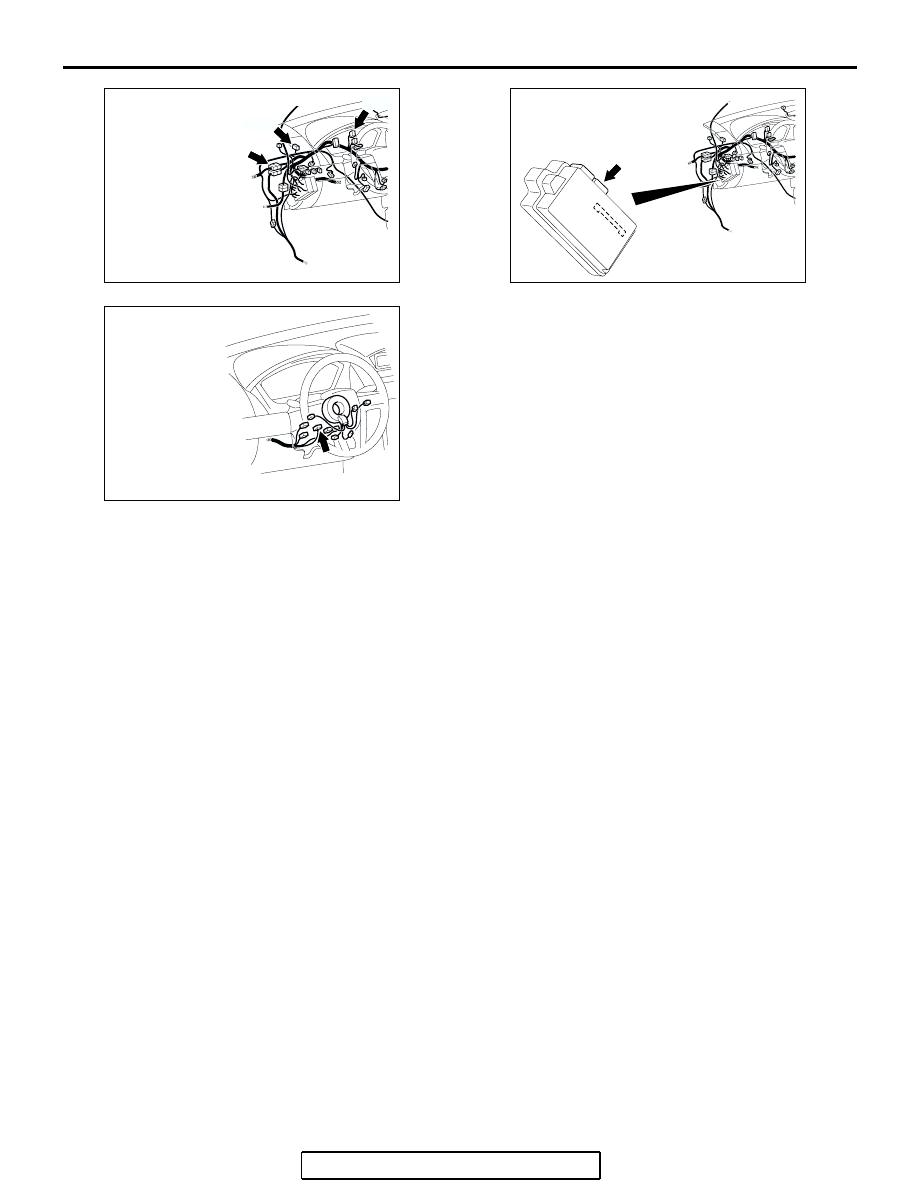
CONNECTORS: C-01, C-03, C-29

AC305413AL

CONNECTOR: C-218

C-218 (GR)

AC305235AC

CONNECTOR: C-309

SYMPTOM PROCEDURES

TSB Revision

SIMPLIFIED WIRING SYSTEM (SWS)

54B-73

STEP 1. Use scan tool MB991958 to select "ECU COMM 
Check" on the SWS monitor display. 
Check the following ECUs:

• ETACS-ECU

• Column-ECU

CAUTION

To prevent damage to scan tool MB991958, always turn the 
ignition switch to the "LOCK" (OFF) position before con-
necting or disconnecting scan tool MB991958. Connect 
special tool MB991910 before connecting special tool 
MB991812. Be sure to connect special tool MB991806 after 
turning on special tool MB991824.
(1) Connect the special tool. Refer to "How to connect SWS 

monitor 

P.54B-13

."

(2) Turn the ignition switch to the "ON" position.
(3) Operate scan tool MB991958 according to the procedure 

below to display "ECU COMM Check."
a. Select "Interactive Diagnosis."
b. Select "System select."
c. Select "SWS."
d. Select "SWS MONITOR."
e. Select "ECU COMM Check."

(4) Scan tool MB991958 should show "OK" on the "ECU 

COMM Check" menus for both the "ETACS ECU" and the 
"COLUMN ECU" menus.

Q: Is "OK" displayed for both the "ETACS ECU" and 

"COLUMN ECU" menus?
"OK" is displayed for all the items : 
Go to Step 2.
"NG" is displayed for the "COLUMN ECU" menu : Go to 

Step 6.

"NG" is displayed for the "ETACS ECU" menu : Refer to 

Inspection Procedure A-3 "Communication with the 
ETACS-ECU is not possible 

P.54B-78

."

"NG" is displayed for all the items : Refer to Inspection 

Procedure A-3 "Communication with the ETACS-ECU 
is not possible 

P.54B-78

."

AC305411AB

MB991910

DATA LINK

CONNECTOR

MB991827

MB991824

MB991806

MB991812

AC302210

COLUMN SWITCH 
CONNECTOR

COLUMN SWITCH 
CONNECTOR AT 
HARNESS SIDE 

MB991812

AB

SYMPTOM PROCEDURES

TSB Revision

SIMPLIFIED WIRING SYSTEM (SWS)

54B-74

STEP 2. Check column switch connector C-309 for loose, 
corroded or damaged terminals, or terminals pushed back 
in the connector.
Q: Is column switch connector C-309 in good condition?

YES : Go to Step 3.
NO :  Repair or replace the damaged component(s). The 

system should communicate with the column switch 
(column-ECU) normally.

STEP 3. Check the power supply circuit to the column 
switch. Measure the voltage at column switch connector 
C-309.
(1) Disconnect column switch connector C-309 and measure 

the voltage available at the wiring harness side of the 
connector.

(2) Measure the voltage between terminal 1 and ground by 

backprobing.

• The voltage should measure approximately 12 volts 

(battery positive voltage).

Q: Is the measured voltage approximately 12 volts (battery 

positive voltage)?
YES : 
Go to Step 5.
NO :  Go to Step 4.

STEP 4. Check the wiring harness between column switch 
connector C-309 (terminal 1) and the battery.

AC305235

HARNESS SIDE

CONNECTOR: C-309

AE

AC305235

HARNESS SIDE

CONNECTOR: C-309

AE

AC209365FF

CONNECTOR C-309
(HARNESS SIDE)

AC305235

HARNESS SIDE

CONNECTOR: C-309

AE

SYMPTOM PROCEDURES

TSB Revision

SIMPLIFIED WIRING SYSTEM (SWS)

54B-75

NOTE: Also check intermediate connector C-29 and joint con-
nector C-01 for loose, corroded, or damaged terminals, or ter-
minals pushed back in the connector. If intermediate connector 
C-29 or joint connector C-01 is damaged, repair or replace the 
connector as described in GROUP 00E, Harness Connector 
Inspection 

P.00E-2

.

Q: Is the wiring harness between column switch connector 

C-309 (terminal 1) and the battery in good condition?
YES : 
No action is necessary and testing is complete.
NO :  The wiring harness may be damaged or the 

connector(s) may have loose, corroded or damaged 
terminals, or terminals pushed back in the connector. 
Repair the wiring harness as necessary. The system 
should communicate with the column switch 
(column-ECU) normally.

STEP 5. Check the ground circuit to the column switch. 
Measure the resistance at column switch connector C-309.
(1) Disconnect column switch connector C-309 and measure 

the resistance available at the wiring harness side of the 
connector.

(2) Measure the resistance value between terminal 4 and 

ground.

• The resistance should be 2 ohms or less.

Q: Is the measured resistance 2 ohms or less?

YES : Go to Step 7.
NO :  Go to Step 6.

AC305232

CONNECTORS: C-01, C-29

C-01

C-29

C-01

C-29

AK

AC305235

HARNESS SIDE

CONNECTOR: C-309

AE

AC209364GX

CONNECTOR C-309
(HARNESS SIDE)


Content   ..  17  18  19  20   ..