Mitsubishi Galant 9G. Manual - part 17
SYMPTOM PROCEDURES
TSB Revision
SIMPLIFIED WIRING SYSTEM (SWS)
54B-64
SCAN TOOL OR VOLTMETER
If a problem is found in the Pulse Check, observe the
table below.
SYMPTOM PROCEDURES
INSPECTION PROCEDURE A-1: Communication with the SWS Monitor Kit is not Possible.
SYMPTOM
INSPECTION
PROCEDURE
REFERENCE
PAGE
ETACS-ECU does not receive any signal from the key reminder switch.
N-1
ETACS-ECU does not receive any signal from the hazard warning light
switch.
N-2
ETACS-ECU does not receive any signal from any of the door switches.
N-3
ETACS-ECU does not receive any signal from the door lock key cylinder
switch.
N-4
ETACS-ECU does not receive any signal from the front door lock actuator. N-5
ETACS-ECU does not receive any signal from the door lock switch
(incorporated in the power window main switch and front power window
sub switch).
N-6
ETACS-ECU does not receive any signal from the trunk lid latch assembly. N-7
Transmitter
ETACS-ECU does not receive any signal from the lock,
unlock, trunk or panic switch.
N-8
ETACS-ECU does not receive any interior light loaded signal.
N-9
DATA LINK
CONNECTOR
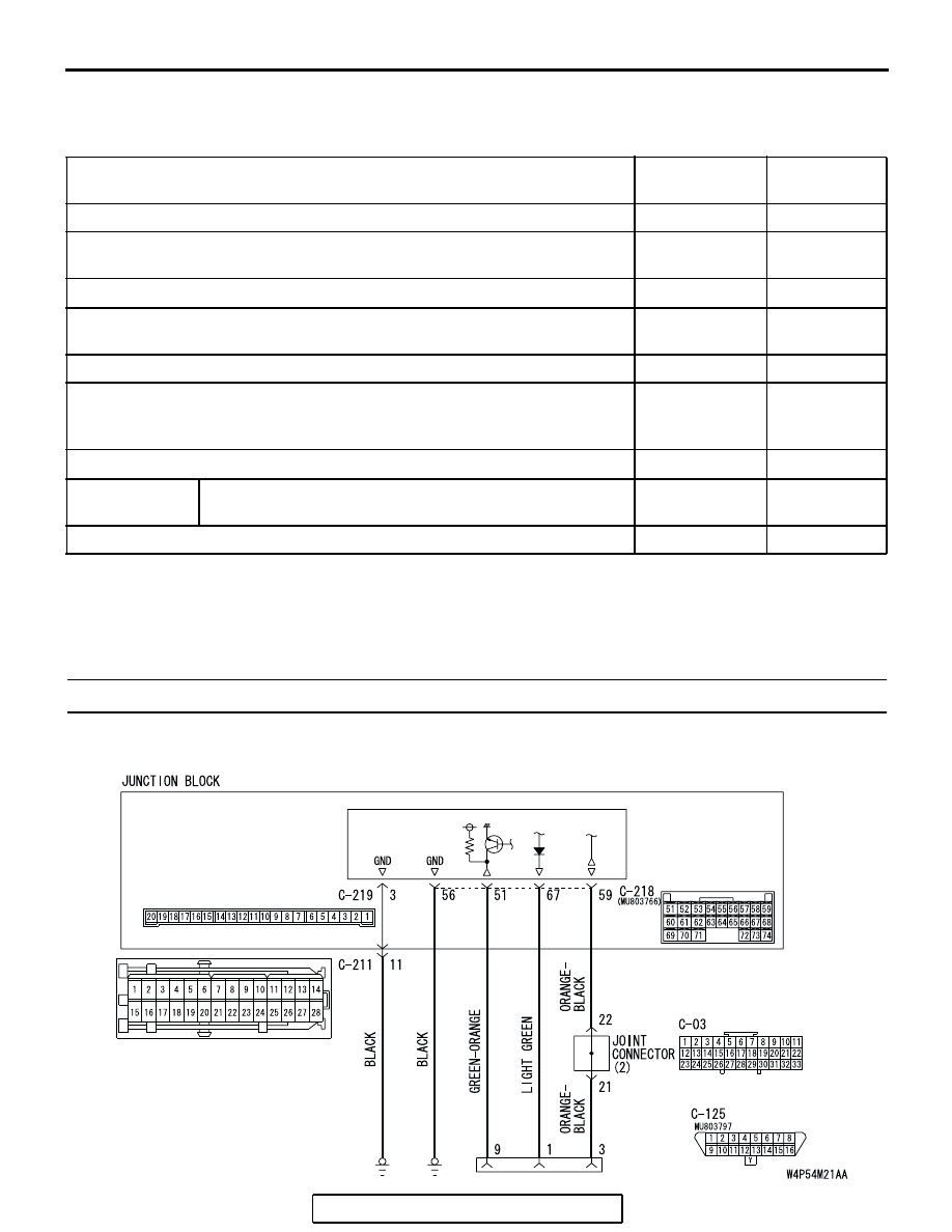
JUNCTION
BLOCK SIDE
FRONT
SIDE
ETACS-
ECU
Scan Tool Communication and ETACS-ECU Ground Circuit