Mitsubishi Pajero Pinin. Manual - part 349
3
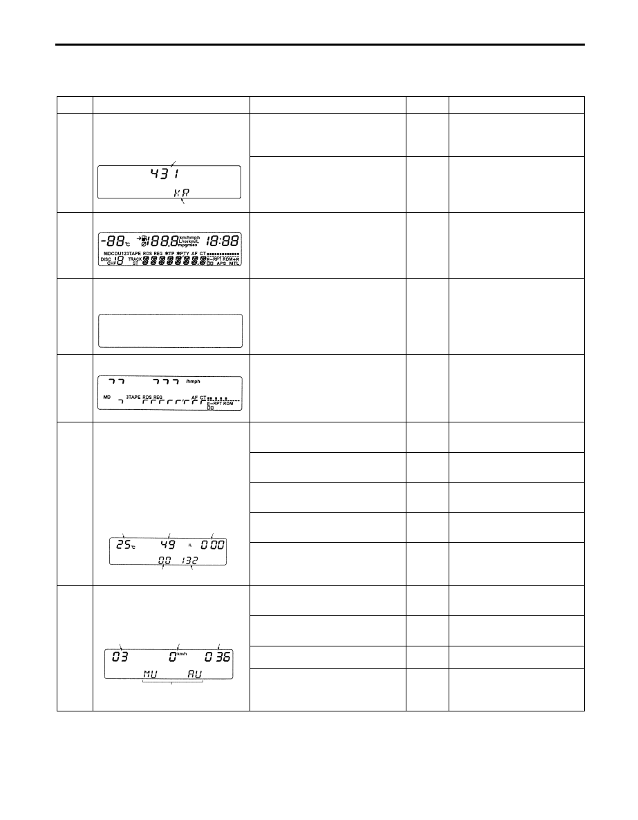
2. Service mode menu and check procedure.
The service mode display changes by pressing “SET” button by following order. (Next to No.9, th
function returns to No.1 and repeats the sequence from No.1.)
No.
Mode and display
Displayed contents
Unit
Checking item
Model name and vehicle type. A. Display model.
Code
Confirm the display model
code. (“431” is displayed
for this vehicle
1
B. Vehicle type.
Code
Confirm the vehicle type.
(“KR” is displayed for this
vehicle.)
2
Segment check.(illuminate)
All segment illuminated.
_
Check defect segments.
3
Segment check. (only back-
lamp)
Back-lamp only. (all segment
off)
_
Check damage, dust etc.
4 - 7
¼ segment check.
Each ¼ segment illuminate.
(4 different displays appear.
The left figure shows the first
display.)
_
Check short circuit.
A. Calculated outside
temperate.
°C
Check the displayed
value.
B. Calculated remaining fuel.
ℓ
Check the displayed
value.*
2
C. Consumed fuel quantity
since.
ℓ
Check the displayed
value.
D. Fuel gauge unit signal
voltage.
V*
1
Check th displayed
value. *
2
8
Temperature sensor and fue
gauge unit signal check
E. IG voltage.
V*
1
Check the displayed
value. (Battery positive
voltage)
A. Voltage of MUT-II
detection input.
%
Connect: more than 80,
Disconnect: less than 50.
B. Calculated vehicle speed.
Km/h
Check the displayed
value.
C. Clock.
Sec
Confirm operating.
9
Clock and connected
components check.
D. Connecting components.
Name
Conform connecte
components (“MU”: MUT-
II< “AU”: audio)
<Added>
A
B
AX0345AL
X0348AL
X0347AL
X0346AL
AX0350AL
A
B
C
D
AY0002AL
D
E
C
B
A