Mitsubishi Pajero Pinin. Manual - part 275


  Index      Mitsubishi     Mitsubishi Pajero Pinin - service repair manual 2001 year


Search            


Content   ..  273  274  275  276   ..


Mitsubishi Pajero Pinin. Manual - part 275


BODY – 

Door

42-26

"

B

A

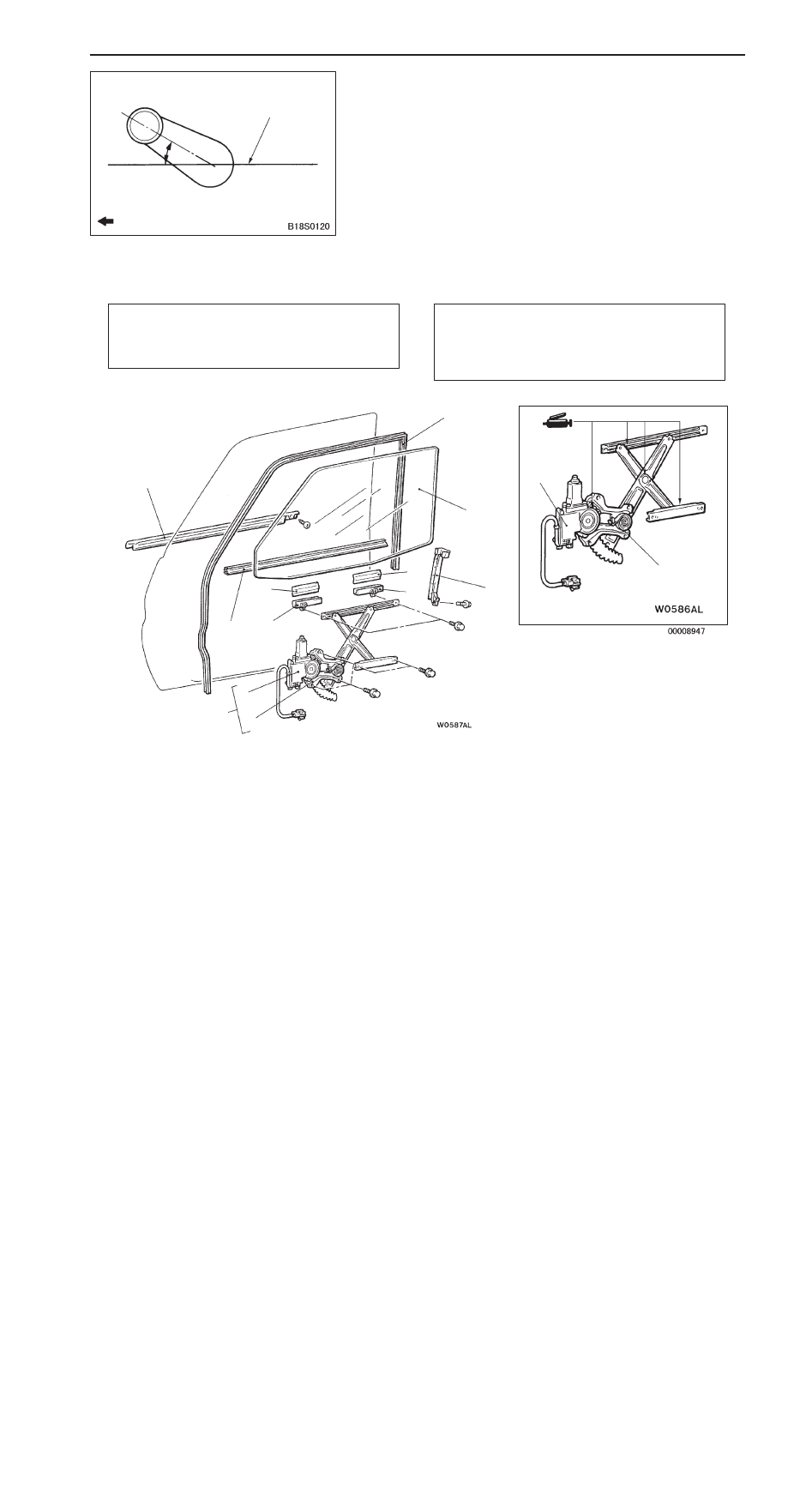
REGULATOR HANDLE/ESCUTCHEON/CLIP
INSTALLATION

1.

Install the clip and escutcheon to the regulator handle.

2.

Close the front door window glass fully, and then install
the regulator handle as shown in the illustration.

DOOR GLASS AND REGULATOR

REMOVAL AND INSTALLATION

Pre-removal Operation

D

Door Mirror Removal (Refer to GROUP 51.)

D

Door Trim and Waterproof Film Removal 
(Refer to P.42-23.)

Post-installation Operation

D

Door Window Glass Adjustment (Refer to P.42-19.)

D

Door Trim and Waterproof Film Installation 
(Refer to P.42-23.)

D

Door Mirror Installation (Refer to GROUP 51.)

7

8

9

7

8

2

1

3

4

10

6

5

6

5

Door window glass removal steps

"

D

A D

limit switch set-up

1. Door window inner weather strip
2. Door belt line moulding assembly
3. Door window glass runchannel

"

C

A

4. Door window glass

"

C

A

5. Glass holder

"

C

A

6. Door glass pad

Power window regulator and motor
assembly removal steps

A

A

"

7. Power window regulator and motor

assembly

"

B

A

8. Power window motor assembly

"

B

A

9. Power window regulator assembly

"

A

A

10. Rear lower sash

Front of vehicle

30

_

Horizontal line

BODY – 

Door

BODY – 

Door

42-27

REMOVAL SERVICE POINT

A

A

"

POWER WINDOW REGULATOR AND MOTOR
ASSEMBLY REMOVAL

1.

Remove the door window glass assembly installation bolts.

2.

Lift up the door window glass assembly, and then install
the special tool to the window glass as shown in the
illustration to prevent the window glass falling.

Caution
If a film, etc. is attached to the door window glass,
install the special tool to the outside of window glass
in order to prevent the film peeling.

3.

Remove the power window regulator and motor assembly.

INSTALLATION SERVICE POINTS

"

A

A

REAR LOWER SASH INSTALLATION

Be sure to insert the rear lower sash to the window rear sash
(at door) securely.

"

B

A

POWER WINDOW MOTOR ASSEMBLY/POWER
WINDOW REGULATOR ASSEMBLY
INSTALLATION

Adjust the power window motor assembly and power window
regulator assembly positions as follows:
1.

Connect the power window motor assembly connector
and the power window switch connector to the wiring
harness of body side.

2.

Turn on the power window switch to operate the power
window motor for 3 seconds in the direction which the
window glass closes.

3.

Disconnect the power window motor assembly connector
and the power window switch connector from the wiring
harness of body side.

4.

Assemble the power window motor assembly and the
power window regulator so that the arm and bracket are
positioned as shown in the illustration, and then install
the power window motor assembly.

MB990480

Power window
motor assembly

Arm

Bracket

30

°

 or less

BODY – 

Door

BODY – 

Door

42-28

Caution
When installing the power window regulator, do not
set it in the window glass fully-closed position. If
installing the power window regulator in that condition,
the window glass safety mechanism will not functions
correctly.

"

C

A

DOOR WINDOW GLASS/GLASS HOLDER/DOOR
GLASS PAD INSTALLATION

1.

Install the door glass pads and glass holders to the window
glass in the positions shown.

Standard value (A): 55.0 mm

Standard value (B): 419.0 – 421.0 mm

Standard value (C): 55.0 mm

2.

Install the glass to the window regulator assembly.

Caution
Do not activate the window regulator assemble before
installing the glass as the resetting in the limit switch
is cancelled.

"

D

A

LIMIT SWITCH SETTING

1.

Fully close the window glass.

NOTE
The limit switch learning operation is complete once the
window glass is fully closed.

2.

Check that the limit switch operates normally. 
(Refer to P.42-20.)

INSPECTION

POWER WINDOW MAIN SWITCH CONTINUITY CHECK

NOTE 
Since the power window main switch uses the SWS system, check the continuity with the input signal
check method. Refer to GROUP 54B – Troubleshooting.

B

C

Glass holders

A

BODY – 

Door

BODY – 

Door

42-29

POWER WINDOW SUB SWITCH CONTINUITY CHECK

Switch 

iti

Terminal No.

position

1

4

6

UP

DOWN

POWER WINDOW RELAY CONTINUITY CHECK

Battery

lt

Terminal No.

y

voltage

1

3

4

5

Not applied

Applied

Power window
relay


Content   ..  273  274  275  276   ..