Mitsubishi Pajero Pinin. Manual - part 274
BODY –
Door
BODY –
Door
42-22
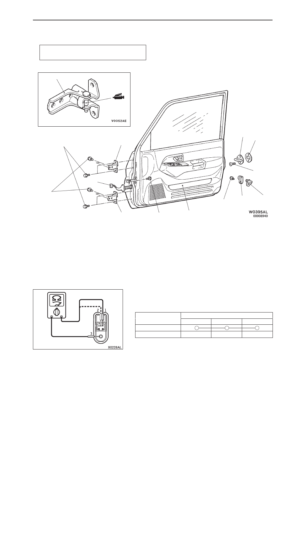
DOOR ASSEMBLY
REMOVAL AND INSTALLATION
Post-installation Operation
Door Fit Adjustment (Refer to P.42-19.)
21 Nm
23 Nm
6
7
9
8
3
4, 5
4
1
5
2
15 Nm
12 Nm
Door assembly removal steps
1. Harness connector
2. Door check connecting bolt
3. Door assembly
4. Door upper hinge
5. Door lower hinge
Striker removal steps
6. Striker
7. Striker shim
Door switch removal steps
8. Door switch cap
9. Door switch
INSPECTION
DOOR SWITCH CONTINUITY CHECK
Driver’s side
Switch
Terminal number
Switch
position
1
2
3
(Earth)
Released (ON)
Depressed (OFF)