Mitsubishi Pajero Pinin. Manual - part 267


  Index      Mitsubishi     Mitsubishi Pajero Pinin - service repair manual 2001 year


Search            


Content   ..  265  266  267  268   ..


Mitsubishi Pajero Pinin. Manual - part 267


STEERING – 

Power Steering Oil Pump

STEERING – 

Power Steering Oil Pump

STEERING – 

Power Steering Oil Pump

37A-29

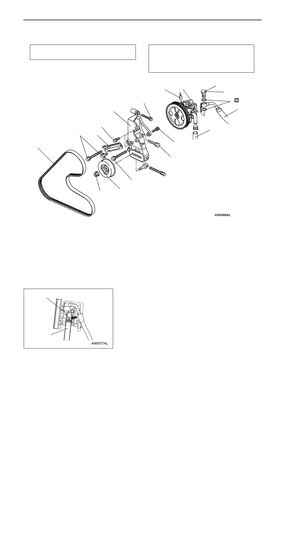
POWER STEERING OIL PUMP

REMOVAL AND INSTALLATION

Pre-removal Operation
Power Steering Fluid Draining (Refer to P.37A-9.)

Post-installation Operation

D

Power Steering Fluid Supplying and Bleeding
(Refer to P.37A-9.)

D

Drive Belt Tension Adjusting 
(Refer to GROUP 11A.)

1

3

4

9

28  Nm

8

57  Nm

28  Nm

49  Nm

5

7

6

25  Nm

44  Nm

10

44  Nm

21  Nm

2

7

Removal steps

D

Air intake duct

1. Drive belt
2. Pressure switch connector
3. Eye bolt
4. Pressure hose
5. Gasket

"

A

A

6. Suction hose
7. Oil pump assembly
8. Oil pump stay
9. Tensioner pulley

10. Oil pump bracket

INSTALLATION SERVICE POINT

"

A

A

SUCTION HOSE INSTALLATION

Install so that the mark on the suction hose is positioned as
shown.

Oil pump

Suction hose

STEERING – 

Power Steering Oil Pump

37A-30

DISASSEMBLY AND REASSEMBLY

Oil pump seal kit

Oil pump cartridge kit

Oil pump pulley and shaft kit

1

3

4

9

10

11

25 – 29 Nm

8

59 Nm

12 Nm

27 Nm

2

5

6

7

12

13

14

15

16

17

5

2

9

12

17

10

14

5

7

4

3

8

5

6

NOTE

     : Automatic transmission fluid DEXRON or DEXRON 

II

Caution
Never disassemble the terminal 

assembly unable to be reassembled.

Disassembly steps

1. Pump cover
2. O-ring

"

E

A

3. Vanes

"

D

A

4. Cam ring
5. Snap ring
6. Pulley and shaft

"

C

A

7. Rotor
8. Side plate

"

A

A

9. O-ring

"

B

A

10. Oil seal

11. Terminal assembly

"

A

A

12. O-ring
13. Inner plug

"

A

A

14. O-ring
15. Flow control spring
16. Suction connector

"

A

A

17. O-ring

STEERING – 

Power Steering Oil Pump

37A-31

REASSEMBLY SERVICE POINTS

"

A

A

O-RING INSTALLATION

No.

ID 

×

 Width mm

1

21.0 

×

1.9

2

14.8 

×

2.4

3

14.8 

×

1.9

4

3.8 

×

 1.9

5

15.8 

×

2.4

"

B

A

OIL SEAL INSTALLATION

"

C

A

ROTOR INSTALLATION

Install the rotor with its punch mark towards the side plate.

"

D

A

CAM RING INSTALLATION

Install the cam ring with its identification mark towards the
side plate.

Inner plug

Side plate

Terminal assembly

Suction connector
mounting portion of
oil pump body

1

3

5

2

4

MB990938

MB991203

Punch mark

Identification
mark

STEERING – 

Power Steering Oil Pump/Power Steering Oil Hoses

37A-32

"

E

A

VANE INSTALLATION

Install the vane to the rotor with its round edge outwards
(towards cam ring).

POWER STEERING OIL HOSES

REMOVAL AND INSTALLATION

Pre–removal and Post–installation Operations

D

Power Steering Fluid Draining and Supplying, and
Bleeding (Refer to P.37A–9.)

D

Under Cover Removal and Installation

D

Air Intake Hose, Resonator, Air Duct, Air Cleaner
Cover Removal and Installation
(Refer to GROUP 15.)

Vane

Round
edge


Content   ..  265  266  267  268   ..