Mitsubishi Pajero Pinin. Manual - part 266


  Index      Mitsubishi     Mitsubishi Pajero Pinin - service repair manual 2001 year


Search            


Content   ..  264  265  266  267   ..


Mitsubishi Pajero Pinin. Manual - part 266


STEERING – 

Power Steering Gear Box and Linkage

37A-25

Caution
Do not use Dia Queen ATF SP

II 

and


ATF SP

II 

M


as

they damage the components of the power steering.

2.

Apply the specified fluid to the oil seal inner surface and
the O-ring.

Specified fluid:

Automatic transmission fluid
DEXRON or DEXRON 

II

Caution
Do not use Dia Queen ATF SP

II 

and


ATF SP

II 

M


as

they damage the components of the power steering.

3.

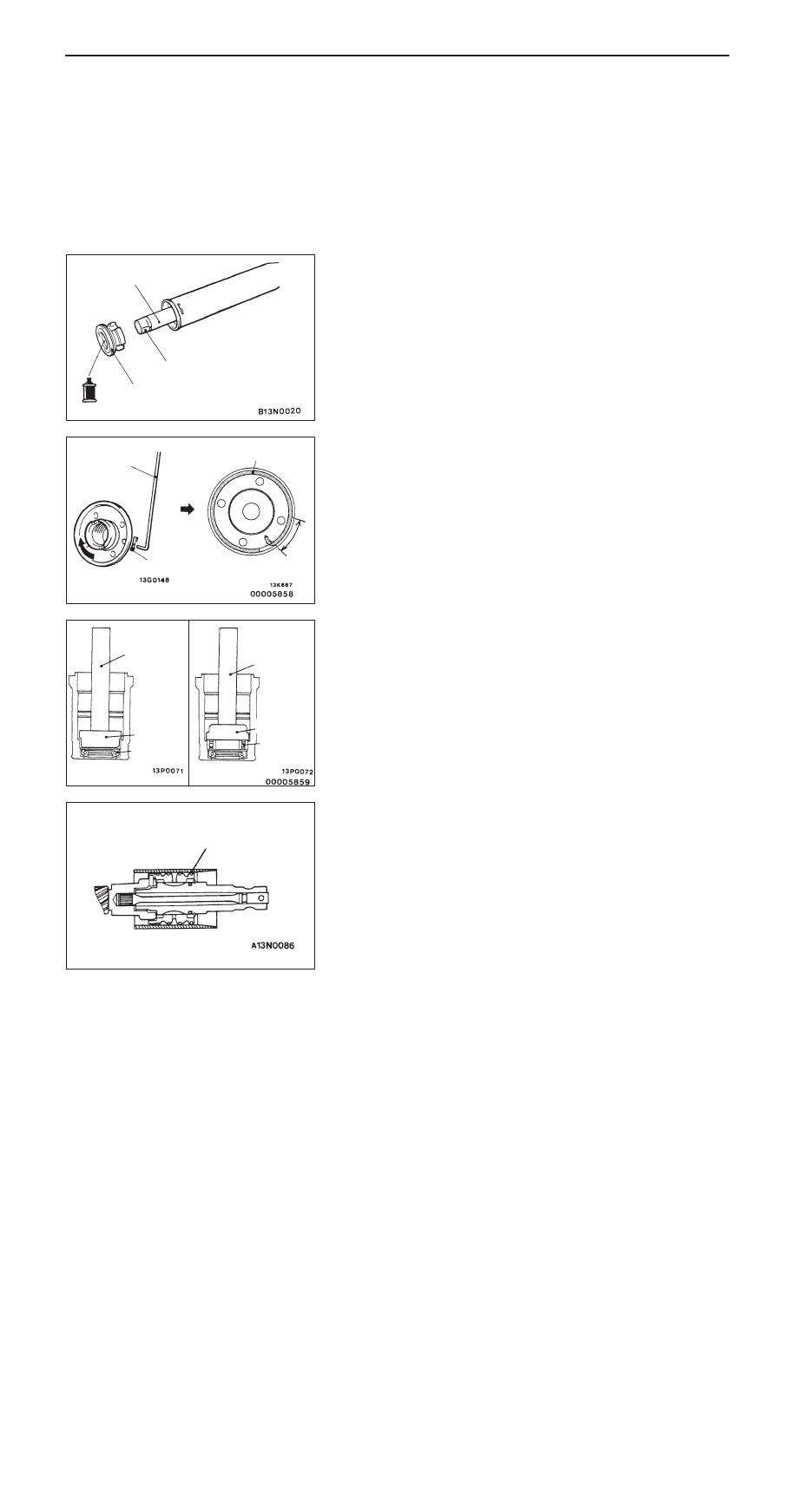
Wrap the rack end with plastic tape, and push the rack
bushing onto the rack.

"

E

A

CIRCLIP INSTALLATION

Align the mark on the rack stopper and the slot in the cylinder.
Then, insert the circlip into the rack stopper hole through the
cylinder hole. Turn the rack stopper clockwise and insert the
circlip firmly.

"

F

A

UPPER OIL SEAL/UPPER BEARING
INSTALLATION

"

G

A

SEAL RING INSTALLATION

After installation, using the special tool or by hand, compress
seal rings that expand during installation.

Rack bushing

Plastic tape

Rack

Circlip

Slot

Circlip

Slot

Upper oil
seal

MB990925
(MB990938)

MB990925
(MB990938)

MB991203

MB991203

Bearing

MB991317

STEERING – 

Power Steering Gear Box and Linkage

37A-26

"

H

A

LOWER OIL SEAL INSTALLATION

Using the special tool, press the oil seal into the valve housing.
The upper surface of the oil seal must project outwards about
1 mm from the housing end surface.

Caution
When the oil seal is flush with or lower than the housing
edge, reassemble the components. Otherwise, oil leaks
will result.

"

I

A

RACK SUPPORT COVER/LOCKING NUT
INSTALLATION

1.

Apply specified sealant to the rack cover support thread.

Specified fluid:

3M ATD Part No.8661 or equivalent

2.

Using the special tool, tighten the rack support cover to
22 Nm.

3.

Return the rack support cover by about 30

_

.

4.

Tighten the locking nut to the specified torque, using the
special tool to prevent the rack support cover from spinning.

"

J

A

PINION TOTAL ROTATION TORQUE ADJUSTMENT

1.

Using the special tool, measure total rotation torque by
turning the pinion gear at a speed of one rotation per
4 to 6 seconds.

Standard value:

Total rotation torque: 0.6 – 1.5 Nm
Torque fluctuation: 0.5 Nm or less

2.

If the total rotation torque or torque fluctuation does not
meet the standard values, adjust by returning the rack
support cover within a range of 0 to 30

_

.

Caution
(1) Adjust around the maximum limit of the standard

values.

(2) See that no ratcheting or catching are present

when operating the rack towards the shaft
direction.

(3) Measure the total pinion torque through the whole

stroke of the rack.

3.

If the adjustment is impossible in the given range, check
the components of the rack support cover, and replace
if necessary.

Approx. 1 mm

MB990941

Oil
seal

Housing

MB991621

MB991006

STEERING – 

Power Steering Gear Box and Linkage

37A-27

"

K

A

TAB WASHER/TIE ROD INSTALLATION

After installing the tie rod to the rack, fold the tab washer
end (2 locations) to the tie rod notch.

"

L

A

BELLOWS BAND INSTALLATION

1.

Turn the adjusting bolt of the special tool to adjust the
opening dimension (W) to the standard value.

Standard value (W): 2.9 mm

<When more than 2.9 mm>
Screw in the adjusting bolt.
<When less than 2.9 mm>
Loosen the adjusting bolt.

NOTE
(1) The dimension (W) is adjusted by about 0.7 mm per

one turn.

(2) Do not turn the adjusting bolt more than one turn.

2.

Use the special tool to crimp the bellows band.

Caution
(1) Hold the rack housing, and use the special tool

to crimp the bellows band securely.

(2) Crimp the bellows band until the special tool

touches the stopper.

3.

See that the crimped width (A) meets the standard value.

Standard value (A): 2.4 – 2.8 mm

<When more than 2.8 mm>
Readjust the dimension (W) of step (1) to the value
calculated by the following equation, and repeat step
(2).

W = 5.5 mm – A [Example: If (A) is 2.9 mm, (W)
is 2.6 mm.]

<When less than 2.4 mm>
Remove the bellows band, readjust the dimension
(W) of step (1) to the value calculated by the following
equation, and use a new bellows band to repeat steps
(2) to (3).

W = 5.5 mm – A [Example: If (A) is 2.3 mm, (W)
is 3.2 mm.]

MB991561

Stopper

Adjusting bolt

W

MB991561

A

STEERING – 

Power Steering Gear Box and Linkage

37A-28

"

M

A

TIE ROD END/LOCKING NUT INSTALLATION

Screw in the tie rod end until the dimension shown is achieved.
Then, temporarily tighten with the locking nut.

NOTE
The locking nut must be tightened securely only after the power
steering gear box and linkage are installed to the vehicle and
toe–in is adjusted.

TIE ROD END BALL JOINT DUST COVER
REPLACEMENT

Only when the dust cover is damaged accidentally during
service work, replace the dust cover as follows:
1.

Apply grease inside a new dust cover.

2.

Using the special tool, press in the dust cover to the tie
rod end.

3.

Check the dust cover for cracks or damage by pushing
it with finger.

Edge of bellows
assembly groove

Locking nut

212 mm

MB990776


Content   ..  264  265  266  267   ..