Mitsubishi Pajero Pinin. Manual - part 211


  Index      Mitsubishi     Mitsubishi Pajero Pinin - service repair manual 2001 year


Search            


Content   ..  209  210  211  212   ..


Mitsubishi Pajero Pinin. Manual - part 211


FRONT AXLE –  

Differential Carrier

26-9

DIFFERENTIAL CARRIER

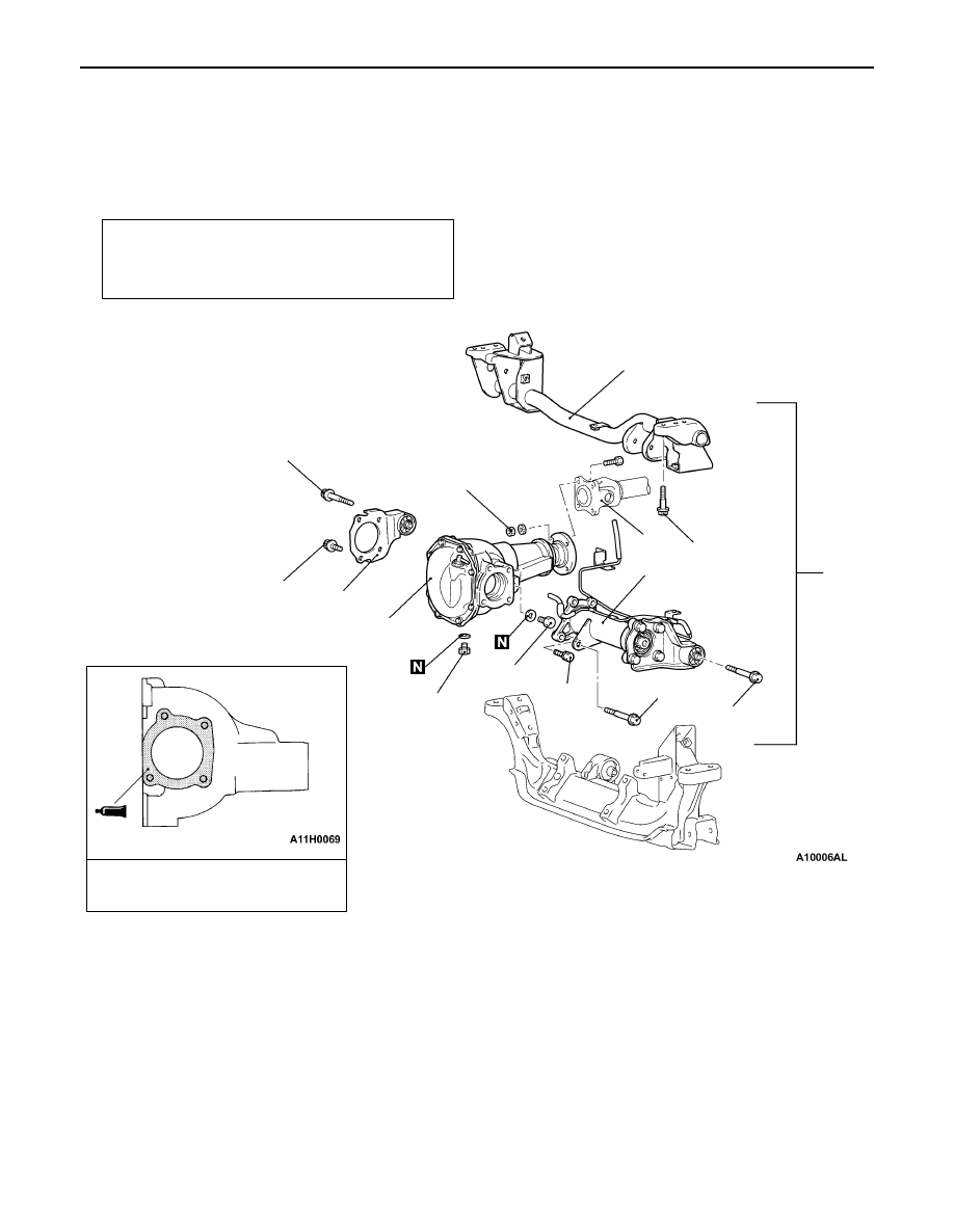
REMOVAL AND INSTALLATION

Caution
To prevent bushings from breakage, the parts indicated by * should be temporarily tightened, and then fully
tightened with the vehicle on the ground in the unladen condition.

Pre-removal and Post-installation Operation

D

Drive Shaft Removal and Installation

D

Stabilizer Bar Removal and Installation

D

Gear Oil Draining and Refilling

Sealant:

3M ATD Part No.8661 or
equivalent

4

5

2

6

1

3

93 

±

 15 N·m*

88 

±

 5 N·m

54 

±

 4 N·m

103 

±

 15 N·m

93 

±

 15 N·m*

108 

±

 10 N·m*

88 

±

 10

N·m

49 

±

 9 N·m

64 

±

 4 N·m

Removal steps

A

A

"

D

Support the Engine Assembly

1. Front propeller shaft connection
2. Front differential assembly and 

differential mount crossmember 
assembly

3. Front axle assembly
4. Differential mount bracket assembly

<RH>

5. Differential carrier
6. Differential mount crossmember 

assembly

NOTE
Removal service points are the same as before.

FRONT AXLE –  

Differential Carrier

FRONT AXLE –  

Differential Carrier

FRONT AXLE –  

Differential Carrier

26-10

DISASSEMBLY AND REASSEMBLY

Service procedures except following are the same as before.

REASSEMBLY SERVICE POINTS

"

D

A

DRIVE PINION HEIGHT ADJUSTMENT

Adjust the drive pinion height by the following procedure.
1.

Apply multipurpose grease to the washer of the special
tool.

2.

Install the special tool, drive pinion front and rear bearing
inner races to the gear carrier.

3.

Tighten the nut of the special tool while measuring the
rotation torque of the drive pinion. Gradually keep
tightening the nut of the special tool until the rotation torque
of the drive pinion (without oil seal) is at the standard
value.

Standard value:

Bearing division

Bearing lubrication

Rotation torque
N·m

New

None (With
anti-rust agent)

0.88 –  1.17

New or reused

Gear oil applied

0.39 –  0.49

NOTE
The special tool cannot be turned a full revolution, so
turn it several times within the range of movement to run
in the bearing, and then measure the rotation torque.

4.

Clean the side bearing hub.

5.

Install the special tools to the side bearing hub of the
gear carrier, and then install the bearing cap.

NOTE
Always check that the notch is in the shown position and
that the special tools are touching firmly against the side
bearing hub.

6.

Use a thickness gauge to measure the clearance (A)
between the special tools.

MB990835

MB990836
(MB990835)

Washer

MB990835

MB990326

Notch

Thickness 
gauge

A

MB990392

MB990836

FRONT AXLE –  

Differential Carrier

26-11

7.

Remove the special tools.

8.

Use a micrometer to measure the special tool in the places
(B, C) shown in the illustration.

9.

Install the bearing cap, and then use a cylinder gauge
and micrometer to measure the inside diameter (D) of
the bearing cap as shown in the illustration.

10. Calculate the thickness (E) of the required drive pinion

front shim by the following formula, and then select a
shim which most closely matches this thickness.

E = A + B + C –  1/2D –  86.0

11. Fit the selected drive pinion front shim(s) to the drive pinion,

and press-fit the drive pinion front bearing inner race by
using the special tool.

"

E

A

DRIVE PINION ROTATION TORQUE
ADJUSTMENT

Adjust the drive pinion rotation torque by using the following
procedure:

1.

Insert the drive pinion into the gear carrier, and then install
the drive pinion spacer, the drive pinion rear shim, the
drive pinion rear bearing inner race, and the companion
flange in that order.

NOTE
Do not install the oil seal.

2.

Use the special tool to hold companion flange, and then
tighten the self-locking nut to the specified torque.

B

C

D

Bearing cap

Drive
pinion
front
shim

MB990829

MB990829

186

±

29 N·m

MB990850

FRONT AXLE –  

Differential Carrier

26-12

3.

Measure the drive pinion rotation torque (without the oil
seal) by using the special tool.

Standard value:

Bearing division

Bearing lubrication

Rotation torque
N·m

New

None (With
anti-rust agent)

0.88 –  1.17

New/reused

Gear oil applied

0.39 –  0.49

4.

If the drive pinion rotation torque is not within the range
of the standard value, adjust it by replacing the drive pinion
rear shim(s) or the drive pinion spacer.

NOTE
When selecting the drive pinion rear shims, if the number
of shims is large, reduce the number of shims to a minimum
by selecting the drive pinion spacers. Also, select the drive
pinion spacer from the following two types.

Drive pinion spacer
height (A) mm

Identification colour

57.72

57.08

Red

5.

Remove the companion flange and drive pinion again.
Then, after inserting the drive pinion rear bearing inner
race into the gear carrier, use the special tool to press-fit
the oil seal.

6.

Install the drive pinion assembly and companion flange
with mating marks properly aligned, and use the special
tool to hold the companion flange, and then tighten the
self-locking nut to the specified torque.

MB990326

Identification
colour

A

MB990727

MB990850

186 

±

 29 N·m


Content   ..  209  210  211  212   ..