Mitsubishi Pajero Pinin. Manual - part 186
AUTOMATIC TRANSMISSION –
A/T Key Interlock and Shift Lock Mechanisms
23-54
A/T KEY INTERLOCK AND SHIFT LOCK MECHANISMS
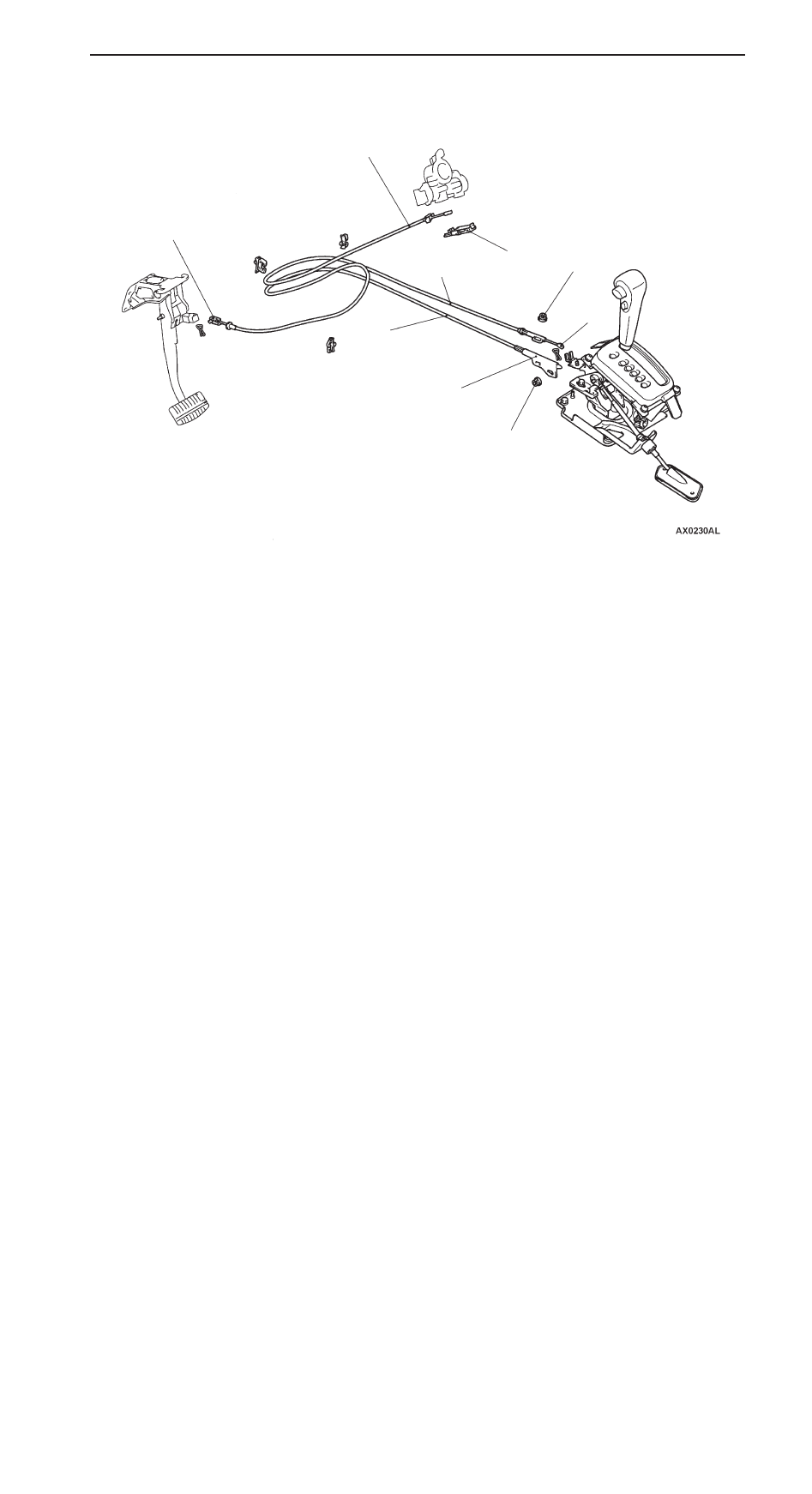
REMOVAL AND INSTALLATION
12 Nm
4
3
2
5
6
7
1
12 Nm
Key interlock cable removal steps
D
Front floor console (Refer to GROUP
52A.)
D
Instrument under cover (Refer to
GROUP 52A.)
D
Lower column cover (Refer to GROUP
37A – Steering Wheel and Shaft.)
"
C
A
1. Key interlock cable connection
(selector lever side)
2. Cover
"
B
A
3. Key interlock cable connection
(steering lock cylinder side)
4. Key interlock cable
Shift lock cable removal steps
D
Front floor console (Refer to GROUP
52A.)
"
A
A
5. Shift lock cable connection
(selector lever side)
6. Shift lock cable connection
(brake pedal side)
7. Shift lock cable