Mitsubishi Pajero Pinin. Manual - part 168
CLUTCH –
Clutch Pedal
21-4
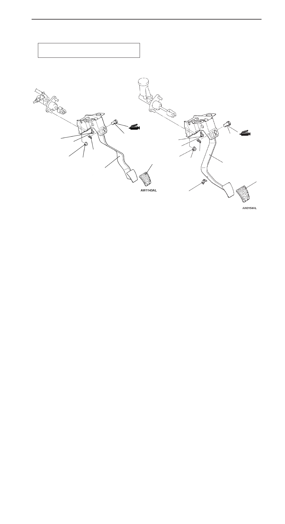
CLUTCH PEDAL
REMOVAL AND INSTALLATION
Post-installation Operation
Clutch Pedal Adjustment (Refer to P.21-2.)
2
4
5
6
7
3
12 Nm
1
12 Nm
L.H. drive vehicles
R.H. drive vehicles
2
4
6
7
3
12 Nm
1
12 Nm
Removal steps
1. Snap pin
2. Clevis pin
3. Clutch master cylinder mounting nut
4. Master cylinder member mounting bolt
5. Stopper <R.H. drive vehicles>
6. Pedal pad
7. Clutch pedal assembly