Mitsubishi Pajero Pinin. Manual - part 143
ENGINE ELECTRICAL –
Charging System
16-2
CHARGING SYSTEM
GENERAL INFORMATION
The charging system uses the alternator output to
keep the battery charged at a constant level under
various electrical loads.
OPERATION
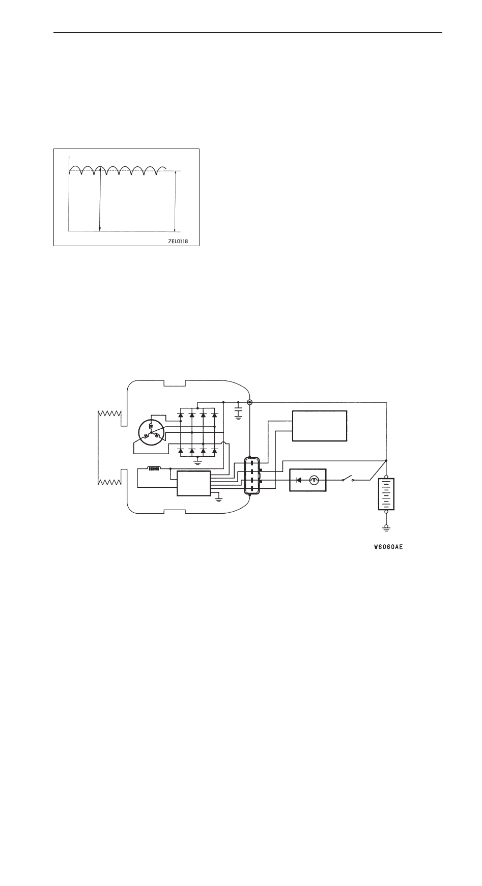
Rotation of the excited field coil generates AC voltage in the
stator.
This alternating current is rectified through diodes to DC voltage
having a waveform shown in the illustration at left. The average
output voltage fluctuates slightly with the alternator load
condition.
When the ignition switch is turned on, current flows
in the field coil and initial excitation of the field coil
occurs.
When the stator coil begins to generate power after
the engine is started, the field coil is excited by
the output current of the stator coil.
The alternator output voltage rises as the field
current increases and it falls as the field current
decreases. When the battery voltage (alternator S
terminal voltage) reaches a regulated voltage of
approx. 14.4 V, the field current is cut off. When
the battery voltage drops below the regulated
voltage, the voltage regulator regulates the output
voltage to a constant level by controlling the field
current.
In addition, when the field current is constant, the
alternator output voltage rises as the engine speed
increases.
SYSTEM DIAGRAM
Stator coil
Field coil
Voltage
regulator
Engine-ECU
Charging
warning lamp
Ignition
switch
Battery
B
G
L
FR
S
+
–
Voltage
Time
Approx. 14.4 V