Mitsubishi Pajero Pinin. Manual - part 141
INTAKE AND EXHAUST –
General/Service Specification/Air Cleaner
15-1
GROUP 15
INTAKE AND EXHAUST
GENERAL
OUTLINE OF CHANGES
The following service procedures have been established due to the addition of vehicle with 4G9-MPI engine.
Other contents are the same as 4G9-GDI engine.
SERVICE SPECIFICATION
Items
Standard value
Limit
Distortion of the intake manifold installation surface mm
0.15 or less
0.20
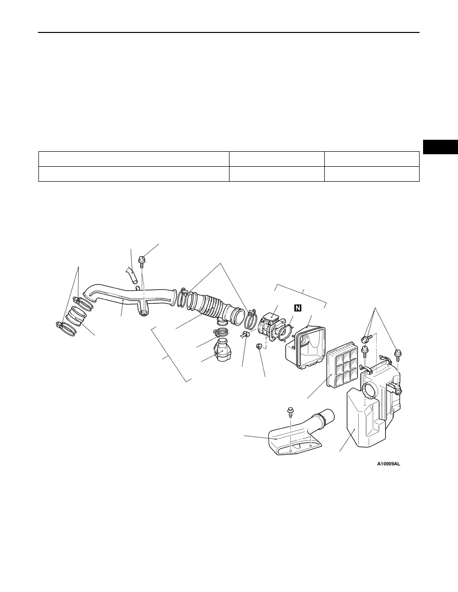
AIR CLEANER
REMOVAL AND INSTALLATION
<4G9-MPI>
1
3
4
5
6
7
9
2
8
10
4.0
±
1.0
N
·
m
12
±
2
N
·
m
3.9
±
1.0
N
·
m
9.0
±
1.0
N
·
m
8.8
±
1.0
N
·
m
3.9
±
1.0
N
·
m
11
12
13
Removal steps
1. Air intake hose and resonator
2. Air intake hose
3. Resonator
4. Air flow sensor connector
5. Air flow sensor and air cleaner cover
6. Air flow sensor
7. Air cleaner cover
8. Air cleaner element
9. Air duct
10. Air cleaner
11. Breather hose connection
12. Air intake pipe
13. Air hose