Mitsubishi Pajero Pinin. Manual - part 26


  Index      Mitsubishi     Mitsubishi Pajero Pinin - service repair manual 2001 year


Search            


Content   ..  24  25  26  27   ..


Mitsubishi Pajero Pinin. Manual - part 26


ENGINE <4G9-MPI> – 

Crankshaft Pulley

11B-15

REMOVAL SERVICE POINT

A

A

"

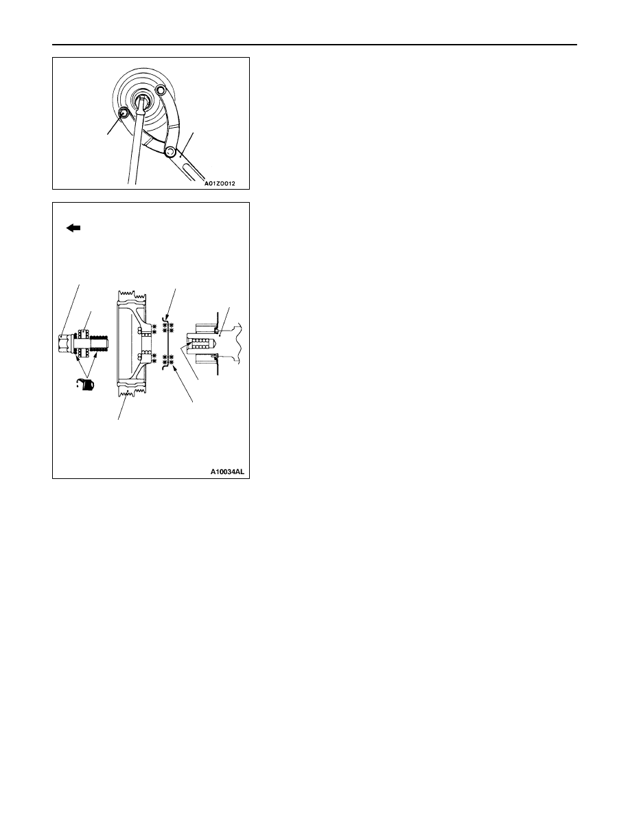
CRANKSHAFT PULLEY REMOVAL

INSTALLATION SERVICE POINT

"

A

A

FRONT FLANGE/CRANKSHAFT PULLEY
INSTALLATION

1.

Clean and then degrease the front flange contacting
surface of the crankshaft pulley.

NOTE
Degreasing is necessary to prevent decrease in the friction
between contacting surfaces.

2.

Clean the bolt hole in the crankshaft, the crankshaft
contacting surface and washer contacting surface of the
crankshaft pulley, and the washer.

3.

Apply an appropriately small amount of oil to the threads
and seating surface of the crankshaft bolt.

4.

Use the special tools to stop the crankshaft pulley from
turning in the same way as was done during removal,
and then tighten the crankshaft bolt to the specified torque.

Tightening torque: 182 

±

 4 N·m

MD998719

MB990767

Front of engine

Crankshaft
bolt

Washer

Crankshaft
pulley

Front
flange

Crankshaft

Clean

Degrease

ENGINE <4G9-MPI> – 

Camshaft and Camshaft Oil Seal

11B-16

CAMSHAFT AND CAMSHAFT OIL SEAL

REMOVAL AND INSTALLATION

1

2

6

3

4

7

5

Apply engine oil to all 
sliding parts at the time
of installation.

31 

±

 3 N·m

14 

±

 1 N·m

22 

±

 4 N·m

10 

±

 2 N·m

88 

±

 10 N·m

Sealant: MITSUBISHI GENUINE
PART MD970389 or equivalent

ø3 mm

5

Camshaft oil seal removal steps

1. Timing belt upper cover

A

A

" "

D

A

2. Camshaft sprocket and timing belt

assembly

"

C

A

3. Camshaft oil seal

Camshaft removal steps

D

Cylinder head assembly
(Refer to P.11B-25.)

A

B

" "

B

A

4. Lash adjuster, rocker arm and shaft

assembly

"

A

A

5. Camshaft position sensor support
6. Camshaft position sensing cylinder
7. Camshaft

REMOVAL SERVICE POINTS

A

A

"

CAMSHAFT SPROCKET AND TIMING BELT
ASSEMBLY REMOVAL

1.

Turn the crankshaft clockwise (right turn) to align the timing
mark and to set the No.1 cylinder at compression top
dead center

Caution
The crankshaft should always be turned only
clockwise.

Timing mark

ENGINE <4G9-MPI> – 

Camshaft and Camshaft Oil Seal

11B-17

2.

Tie the camshaft sprocket and timing belt with a band
cable so that the position of the camshaft sprocket will
not move with respect to the timing belt.

3.

Use the special tools to remove the camshaft sprocket
with the timing belt attached.

Caution
After removing the camshaft sprocket, be sure not
to rotate the crankshaft.

A

B

"

LASH ADJUSTER, ROCKER ARM AND SHAFT
ASSEMBLY REMOVAL

1.

Before removing the lash adjuster, rocker arm and shaft
assembly, install the special tools as shown in the
illustration so that the lash adjusters will not fall out.

2.

Loosen the lash adjuster, rocker arm and shaft assembly
mounting bolt, and then remove the lash adjuster, rocker
arm and shaft assembly with the bolt still attached.

Caution
Never disassemble the lash adjuster, rocker arm and
shaft assembly.

INSTALLATION SERVICE POINTS

"

A

A

CAMSHAFT POSITION SENSOR SUPPORT
INSTALLATION

1.

Remove sealant remained on the camshaft position sensor
support.

2.

Apply sealant to the flange of the camshaft position sensor
support and install to the cylinder head.

Specified sealant: 

MITSUBISHI GENUINE PART MD970389 or 
equivalent

3.

Tighten the camshaft position sensor support mounting
bolt to the specified torque.

Tightening torque: 14 

±

 1 N·m

Camshaft
sprocket

MB990767

MD998719

MD998443

ø3 mm

ENGINE <4G9-MPI> – 

Camshaft and Camshaft Oil Seal

11B-18

"

B

A

LASH ADJUSTER, ROCKER ARM AND SHAFT
ASSEMBLY INSTALLATION

1.

Remove the rocker shaft spring.

2.

Tighten the lash adjuster, rocker arm and shaft assembly
temporarily with mounting bolts so that all the rocker arms
on the intake side will not push the valves.

3.

Install the rocker shaft spring and plug guide so that they
can meet at right angle to each other.

4.

Tighten the lash adjuster, rocker arm and shaft assembly
mounting bolt to the specified torque.

Tightening torque: 31 

±

 3 N·m

5.

Install the the lash adjuster, rocker arm and shaft assembly
on the exhaust side, and then tighten the bolt to the
specified torque.

Tightening torque: 31 

±

 3 N·m

6.

Remove the special tool used for retaining the lash adjuster.

7.

Ensure that the notch at the rocker shaft points towards
the direction as shown in the illustration.

"

C

A

CAMSHAFT OIL SEAL INSTALLATION

1.

Apply engine oil to the camshaft oil seal lip.

2.

Use the special tool to press-fit the camshaft oil seal.

"

D

A

CAMSHAFT SPROCKET AND TIMING BELT
ASSEMBLY INSTALLATION

1.

Use the special tools to stop the camshaft sprocket from
turning in the same way as was done during removal,
and then tighten the camshaft sprocket securing bolt to
the specified torque.

Tightening torque: 88 

±

 10 N·m

2.

Remove the band cable which binds the camshaft sprocket
and timing belt.

Rocker shaft
spring

Plug guide

Notch

Notch

Front of engine

MD998713


Content   ..  24  25  26  27   ..