Mitsubishi Lancer. Manual - part 257
AC006172 AF
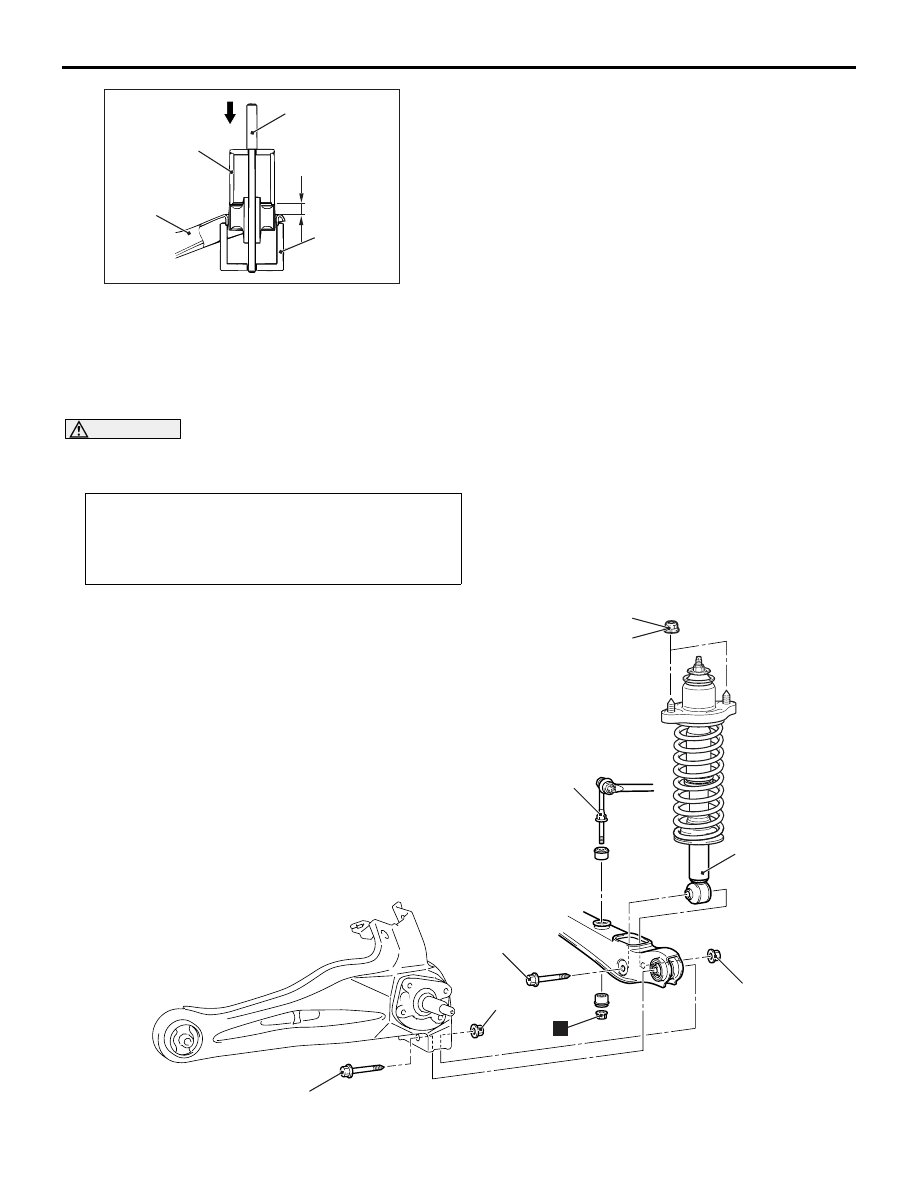
Press-fitting
MB990890
Trailing arm
MB990947
MB991816
16.2 ± 0.5 mm
SHOCK ABSORBER ASSEMBLY
REAR SUSPENSION
34-14
3. Using the special tools, press the trailing arm
bushing into the position shown.
SHOCK ABSORBER ASSEMBLY
REMOVAL AND INSTALLATION
M1341002500261
CAUTION
*
: Indicates parts which should be temporarily tightened, and then fully tightened with the vehicle on
the earth in the unladen condition.
Pre-removal and Post-installation Operation
• Centre Luggage Floor Lid <Wagon> Removal and Instal-
lation
• Centre Luggage Floor Box <Wagon> Removal and Instal-
lation
AC304794 AB
44 ± 5 N·m
2
4
1
3
5
95 ± 15 N·m*
95 ± 15 N·m*
N