Mitsubishi Lancer. Manual - part 258


  Index      Mitsubishi     Mitsubishi Lancer - service repair manual 2006 year


Search            


Content   ..  256  257  258  259   ..


Mitsubishi Lancer. Manual - part 258


SHOCK ABSORBER ASSEMBLY

REAR SUSPENSION

34-18

2. The rear suspension coil spring lower end must 

be positioned as illustrated.

>>C<< REAR SUSPENSION SPRING 
UPPER PAD INSTALLATION

AC304801AC

Spring upper pad
stepped section

Align the stepped section of the spring upper pad 
with the upper end of the coil spring, and install the 
spring upper pad.

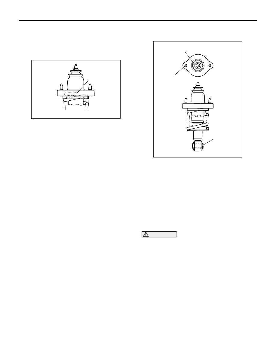
>>D<< REAR SHOCK ABSORBER 
INSULATOR INSTALLATION

AC304802

Lower bushing inner pipe

Rear shock absorber 
insulator mounting bolt

AB

Lower bushing 
inner pipe

Install the rear shock absorber insulator so that the 
axis of the lower bushing inner pipe of the shock 
absorber and the line between the rear shock 
absorber insulator mounting bolts are straight when 
looking from above.

>>E<< REAR SUSPENSION COIL SPRING 
NUT (SELF-LOCKING NUT) 
INSTALLATION

1. Temporarily tighten the rear suspension coil 

spring nut (self-locking nut).

CAUTION

Do not use an impact wrench to tighten the rear 
suspension coil spring nut (self-locking nut), oth-
erwise the piston rod locking nut inside the 
shock absorber will be damaged.
2. Remove the special tools (MB991237, 

MB991239), and then tighten the rear suspension 
coil spring nut (self-locking nut) to 25 

± 5 N⋅ m.

STABILIZER BAR

REAR SUSPENSION

34-19

STABILIZER BAR

REMOVAL AND INSTALLATION

M1341003000258

Post-installation Operation
• Press the dust cover with your finger to check that there 

are no cracks or damage in the dust cover.

AC304232

AC107102

AB

12 ± 2 N·m

39 ± 5 N·m

4

5

6

7

25 ± 4 N·m

Specified grease:
     Multipurpose grease SAE J310, 
     NLGI No.2 or equivalent

2

2

3

1

N

3

Removal steps 

>>

B

<<

1.

Self-locking nut

2.

Stabilizer rubber

3.

Stabilizer link

>>

A

<<

4.

Fixture

>>

A

<<

5.

Bushing

>>

A

<<

6.

Stabilizer bar

7.

Stabilizer bracket

INSTALLATION SERVICE POINTS
>>A<< STABILIZER BAR/BUSHING/FIX-
TURE INSTALLATION

AC102279

AC

Outside of vehicle

Bushing (LH)

Fixture (LH)

Identification colour

Approximately
9.5 mm

Install the stabilizer bar, the bushings and the fixtures 
as illustrated.

>>B<< SELF-LOCKING NUT 
INSTALLATION

AC103744

A

AC

Tighten the self-locking nut until the stabilizer link 
thread part protruding length meets the standard 
value.

Standard value (A): 6 

 8 mm

INSPECTION

M1341001400294

• Check the bushings for wear and deterioration.

• Check the stabilizer bar for deterioration or dam-

age.

• Check all bolts for condition and straightness.

STABILIZER BAR

REAR SUSPENSION

34-20

STABILIZER LINK BALL JOINT TURNING 
TORQUE CHECK

AC001129

MB990326

AB

1. After shaking the ball joint stud several times, 

install the nut to the stud and use special tool 
preload socket (MB990326) to measure the 
turning torque of the ball joint.

Standard value: 0.5 

 1.5 N⋅ m

2. If the measured value exceeds the standard 

value, replace the stabilizer link.

3. If the measured value is lower than the standard 

value, check that the ball joint turns smoothly 
without excessive play. If so, it is possible to 
re-use that ball joint.

STABILIZER LINK BALL JOINT DUST 
COVER CHECK

1. Check the dust cover for cracks or damage by 

pushing it with your finger.

2. If the dust cover is cracked or damaged, replace 

the stabilizer link.

NOTE: Cracks or damage of the dust cover may 
cause damage to the ball joint. When it is dam-
aged during service work, replace the dust cover 
(Refer to 

P.34-20

).

STABILIZER LINK BALL JOINT DUST 
COVER REPLACEMENT

M1341010900242

Only when the dust cover is damaged accidentally 
during service work, replace the dust cover as fol-
lows:

AC006188AB

Clip ring

1. Remove the clip ring and the dust cover.
2. Apply specified grease to the inside of a new dust 

cover.

Specified grease: Multipurpose grease SAE 
J310, NLGI No.2 or equivalent

3. Wrap plastic tape around the stabilizer link stud, 

and then install the dust cover to the stabilizer 
link.

4. Secure the dust cover by the clip ring. 
5. Check the dust cover for cracks or damage by 

pushing it with finger.

14-1

GROUP 14

ENGINE COOLING

CONTENTS

GENERAL INFORMATION . . . . . . . .

14-2

SERVICE SPECIFICATIONS. . . . . . .

14-2

LUBRICANT. . . . . . . . . . . . . . . . . . . .

14-3

SEALANTS  . . . . . . . . . . . . . . . . . . . .

14-3

SPECIAL TOOLS. . . . . . . . . . . . . . . .

14-3

TROUBLESHOOTING . . . . . . . . . . . .

14-5

INSPECTION CHART FOR TROUBLE 


SYMPTOMS . . . . . . . . . . . . . . . . . . . . . . . . 

14-5

INSPECTION PROCEDURE FOR 


TROUBLE SYMPTOMS . . . . . . . . . . . . . . . 

14-6

ON-VEHICLE SERVICE. . . . . . . . . . .

14-21

ENGINE COOLANT LEAK CHECK  . . . . . . 

14-21

RADIATOR CAP VALVE OPENING 


PRESSURE CHECK. . . . . . . . . . . . . . . . . . 

14-21

ENGINE COOLANT REPLACEMENT  . . . . 

14-21

CONCENTRATION MEASUREMENT . . . . 

14-22

COOLING FAN MOTOR DRIVE 


CONTROL UNIT CHECK  . . . . . . . . . . . . . . 

14-22

FAN CONTROL RELAY CONTINUITY 


CHECK  . . . . . . . . . . . . . . . . . . . . . . . . . . . . 

14-23

COOLING FAN MOTOR CHECK  . . . . . . . . 

14-24

THERMOSTAT . . . . . . . . . . . . . . . . . .

14-24

REMOVAL AND INSTALLATION  . . . . . . . . 

14-24

INSPECTION. . . . . . . . . . . . . . . . . . . . . . . . 

14-26

WATER PUMP  . . . . . . . . . . . . . . . . . .

14-27

REMOVAL AND INSTALLATION <4G1> . . 

14-27

REMOVAL AND INSTALLATION <4G6> . . 

14-28

WATER HOSE AND WATER PIPE  . .

14-29

REMOVAL AND INSTALLATION <4G1> . . 

14-29

REMOVAL AND INSTALLATION <4G6> . . 

14-31

INSPECTION. . . . . . . . . . . . . . . . . . . . . . . . 

14-32

RADIATOR . . . . . . . . . . . . . . . . . . . . .

14-33

REMOVAL AND INSTALLATION <4G1> . . 

14-33

REMOVAL AND INSTALLATION <4G6> . . 

14-35


Content   ..  256  257  258  259   ..