Mitsubishi Lancer. Manual - part 230


  Index      Mitsubishi     Mitsubishi Lancer - service repair manual 2006 year


Search            


Content   ..  228  229  230  231   ..


Mitsubishi Lancer. Manual - part 230


TRUNK LID

BODY

42-42

3. If there is a difference in height between the side 

outer panels and the side edges of the trunk lid 
panel assembly, check the trunk lid hinges and, if 
necessary, replace them

4. If the clearance around the trunk lid panel 

assembly is not uniform, and the trunk lid can be 
locked and unlocked smoothly, make adjustments 
to the trunk lid bumpers (refer to 

P.42-42

) and 

trunk lid hinges (Refer to 

P.42-42

).

5. If the locking and unlocking of the trunk lid still is 

difficult after making the above adjustments, 
adjust the trunk lid striker (Refer to 

P.42-42

).

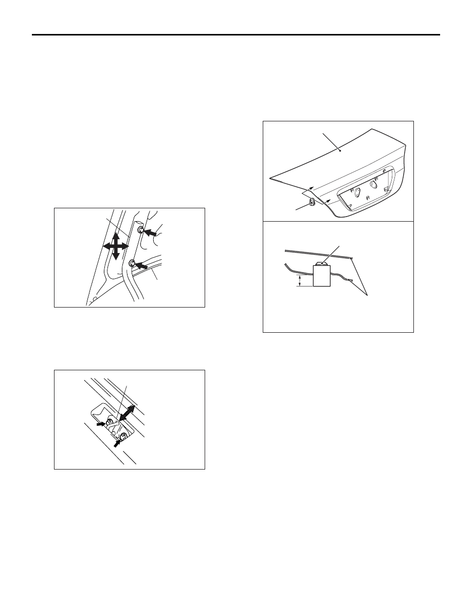
ADJUSTMENT OF CLEARANCE AROUND 
TRUNK LID

M1421008100039

AC202897

Trunk lid panel
assembly

Trunk lid hinge

AB

Loosen the trunk lid panel assembly mounting bolts 
and move the trunk lid panel assembly to make the 
clearance around the trunk lid uniform.

TRUNK LID STRIKER ADJUSTMENT

M1421008200036

AC202898

Trunk lid striker

AB

After checking the trunk lid release cable for proper 
routing, loosen the trunk lid striker mounting bolts. 
Change the position of the trunk lid striker relative to 
the trunk lid latch assembly so that trunk lid locking 
and unlocking effort is correct.

TRUNK LID HEIGHT ADJUSTMENT

M1421008300033

AC305144

Section A - A

Trunk lid bumper

Trunk lid panel assembly

A

A

Trunk lid bumper

Trunk lid panel assembly

AB

14 mm 

Turn each trunk lid bumper until the height shown in 
the drawing is reached. If the trunk lid panel height 
on one side is different from that on the other side 
(even after the trunk lid bumpers have been adjusted 
to the height indicated in the drawing), turn the trunk 
lid bumper(s) slightly to make fine adjustments to the 
trunk lid panel height.
NOTE: When the bumper is new, one full turn of the 
trunk lid bumper changes the height approximately 3 
mm. Turn it clockwise to reduce height. Turn it anti-
clockwise to increase height.

TRUNK LID

BODY

42-43

TRUNK LID

REMOVAL AND INSTALLATION

M1421002200180

AC301676

Y0636AU

Y0637AU

AB

8.9 ± 1.9 N·m

A

A

B

B

15 mm

14 mm

Section A - A

Section B - B

9

5

6

4

12

9

5

9

7

11

10

8

3

5

1

2

Trunk lid weatherstrip removal steps 
• Rear end trim (Refer to GROUP 52A, 

Trims 

P.52A-13

.)

>>

B

<< 1. Trunk lid weatherstrip

Trunk lid release cable and trunk lid 
release handle removal steps 
• Rear end trim (Refer to GROUP 52A, 

Trims 

P.52A-13

.)

• Trunk rear side trim (LH) (Refer to 

GROUP 52A, Trims 

P.52A-13

.)

• Front scuff plate (LH) (Refer to 

GROUP 52A, Trims 

P.52A-13

.)

• Cowl side trim (LH) (Refer to GROUP 

52A, Trims 

P.52A-13

.)

• Rear scuff plate (LH) (Refer to 

GROUP 52A, Trims 

P.52A-13

.)

• Centre pillar lower trim (Refer to 

GROUP 52A, Trims 

P.52A-13

.)

• Rear seat (Refer to GROUP 52A, 

Rear seat assembly 

P.52A-30

.)

• Accelerator pedal stopper (Refer to 

GROUP 17, Accelerator pedal 

P.17-3

.)

2. Trunk lid release handle
3. Trunk lid release cable

Trunk lid striker removal steps 
• Rear end trim (Refer to GROUP 52A, 

Trims 

P.52A-13

.)

4. Trunk lid striker
Trunk lid panel removal steps 
• Licence plate garnish (Refer to 

GROUP 51, Garnishes 

P.51-16

.)

5. Trunk lid bumper
• Rear spoiler (Refer to GROUP 51, 

Rear spoiler 

P.51-25

.)

6. Trunk lid lock cylinder
7. Trunk lid latch assembly
8. Trunk lid hinge mounting bolt
9. Trunk lid panel assembly
Trunk lid latch removal 
7. Trunk lid latch assembly
Trunk lid hinge removal steps 
• Rear shelf trim (Refer to GROUP 

52A, Trim

P.52A-13

.)

• Rear seat (Refer to GROUP 52A, 

Rear seat assembly

P.52A-30

.)

9. Trunk lid panel assembly

<<

A

>> >>

A

<< 10. Trunk lid torsion bar (RH)

<<

A

>> >>

A

<< 11. Trunk lid torsion bar (LH)

12. Trunk lid hinge

AC305143 AB

Grease application area

6

2

7

TRUNK LID

BODY

42-44

REMOVAL SERVICE POINT
<<A>> TRUNK LID TORSION BAR 
REMOVAL

AC205068

AC205068

MB991244

Trunk lid torsion bar <RH>

Trunk lid torsion bar <LH>

AB

1. Attach the special tool to the illustrated portion of 

the trunk lid torsion bar <RH> on the left hand of 
the vehicle, then use the tool to detach the trunk 
lid torsion bar <RH> from the trunk lid hinge <LH>

2. Remove the trunk lid torsion bar <LH> in the 

same way as the trunk lid torsion bar <RH>.

INSTALLATION SERVICE POINTS
>>A<< TRUNK LID TORSION BAR 
INSTALLATION

AC305282

Trunk lid torsion bar <RH>

Trunk lid torsion bar <LH>

Colour mark

A

B

Trunk lid hinge <LH>

Trunk lid torsion bar <LH>

View F

Trunk lid hinge <RH>

Hole

F

E

A

D C

B

MB991244

Trunk lid torsion bar
<LH>

AB

Install the trunk lid torsion bars using the following 
procedure.

TRUNK LID

BODY

42-45

CAUTION

Install the trunk lid torsion bar <LH> before the 
trunk lid torsion bar <RH>. If the sequence is 
reversed, the trunk lid torsion bar <LH> will not 
be able to be installed because the special tool 
will interfere with the trunk lid torsion bar <RH> 
during installation of the trunk lid torsion bar 
<LH>.
1. Identify the LH and RH torsion bars by the colour 

mark made at the centre of each torsion bar.

Trunk lid torsion bar

Mark 
colour

LH

Vehicles with rear spoiler

Green

Vehicles without rear spoiler

White 
green

RH

Vehicles with rear spoiler

Yellow

Vehicles without rear spoiler

Red

2. Insert the left end of the trunk lid torsion bar <LH> 

in the hole in the trunk lid hinge <LH>.

3. Press portion A of the trunk lid torsion bar <LH> 

right end against point A on the trunk lid hinge 
<RH> as shown in View F in the drawing.

4. Twist the portion B of the trunk lid torsion bar 

<LH> right end using the special tool until it is 
moved from point B and pressed against point C 
of the trunk lid hinge <RH> as shown in View F. 
Then force the portion into point D.

5. Twist the portion A of the trunk lid torsion bar 

<LH> right end until it reaches point E on the trunk 
lid hinge <RH> as shown in View F.

6. Attach the trunk lid torsion bar <RH> to the trunk 

lid hinge <LH> using the same method as the 
trunk lid torsion bar <LH>.

>>B<< TRUNK LID WEATHERSTRIP 
INSTALLATION

AC006104AB

Joint
section

Marking
section

Install the trunk lid weatherstrip so that the marking 
and the joint are aligned with the body centre line,

INSPECTION

M1421004800133

TRUNK LID LATCH SWITCH CONTINUITY 
CHECK

AC305142 AB

Trunk lid latch assembly

Switch position

Tester 
connection

Specified 
condition

ON (Latch open)

− Earth 

Less than 2 
ohms

OFF (Latch shut)

Open circuit


Content   ..  228  229  230  231   ..