Mitsubishi Lancer. Manual - part 229


  Index      Mitsubishi     Mitsubishi Lancer - service repair manual 2006 year


Search            


Content   ..  227  228  229  230   ..


Mitsubishi Lancer. Manual - part 229


DOOR

BODY

42-38

Actuator Switch Check <Driver’s side>

Lever position

Tester 
connection

Specified 
condition

At the "LOCK" 
position

− 2

Less than 2 
ohms

− 3

Open circuit

At the "UNLOCK" 
position

− 2

Open circuit

− 3

Less than 2 
ohms

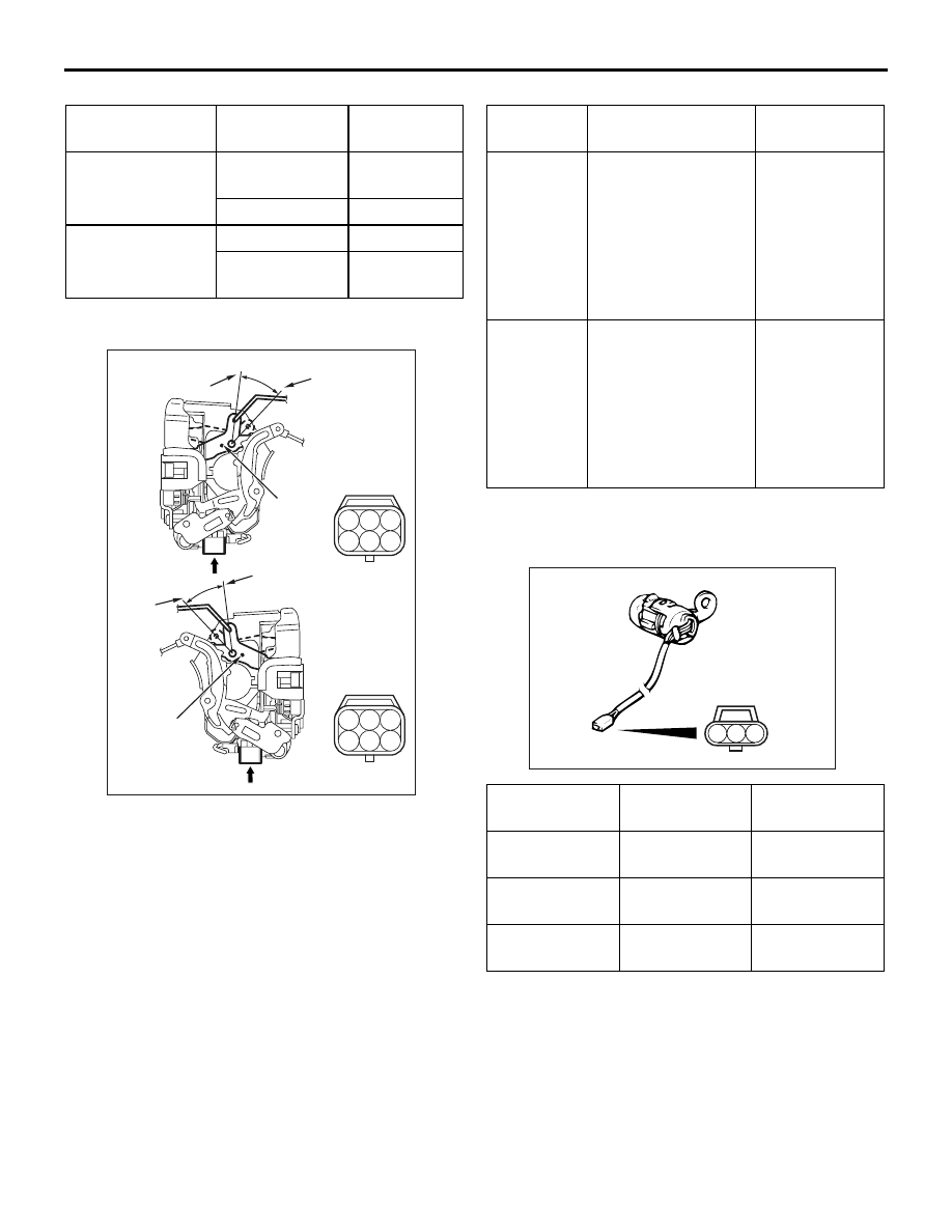
REAR DOOR LOCK ACTUATOR CHECK

2 3

4

1

5 6

2 3

4

1

5 6

AC305112

B

A

AB

Rear door

Lock

Unlock

View A

View B

Unlock

Lock

<Left side>

<Right side>

Lever

Lever

Actuator Operation Check 

Lever 
position

Battery connection Lever 

operation

At the 
"LOCK" 
position

• Connect terminal 

No. 4 and the 
negative battery 
terminal.

• Connect terminal 

No. 6 and the 
positive battery 
terminal.

The lever 
moves from the 
"LOCK" 
position to the 
"UNLOCK" 
position.

At the 
"UNLOCK" 
position

• Connect terminal 

No. 6 and the 
negative battery 
terminal.

• Connect terminal 

No. 4 and the 
positive battery 
terminal.

The lever 
moves from the 
"UNLOCK" 
position to the 
"LOCK" 
position.

DOOR LOCK KEY CYLINDER SWITCH 
CHECK <PASSENGER’S SIDE>

AC101318

3

2

1

Switch 
position

Tester 
connection

Specified 
condition

LOCK

− 3

Less than 2 
ohms

NEUTRAL 
(OFF)

− 2, 2 − 3

Open circuit

UNLOCK

− 2

Less than 2 
ohms

DOOR

BODY

42-39

WINDOW GLASS RUNCHANNEL AND 
DOOR OPENING WEATHERSTRIP

REMOVAL AND INSTALLATION

M1423003100290

<FRONT DOOR>

AC304409AB

Section A – A

<Front door>

Sealant: 3M ATD Part No.8633 or equivalent

Door

: Sectional view of 

 clip position

: Sectional view of 

 clip position

6

2

1

4

3

6

5

A

A

1

Waterproof film removal steps 
• Door trim assembly, speaker (Refer to 

GROUP 52A, Trims 

P.52A-13

).

1. Waterproof film
Door inner opening weatherstrip 
removal steps 
• Scuff plate, centre pillar lower trim 

and cowl side trim (Refer to GROUP 
52A, Trims 

P.52A-13

.)

2. Door inner opening weatherstrip 

(Body side)

Door outer opening weatherstrip 
removal steps 
• Front door check mounting bolt (Door 

side) (Refer to 

P.42-31

.)

<<

A

>> >>

A

<< 3. Door outer opening weatherstrip

Door window glass runchannel 
removal 
4. Door window glass runchannel
Door beltline inner weatherstrip 
removal steps 
• Front door trim(Refer to GROUP 52A, 

Door trim 

P.52A-17

.)

5. Door beltline inner weatherstrip
Door beltline moulding removal steps 
• Door mirror assembly (Refer to 

GROUP 51, Door mirro

P.51-50

.)

• Door window glass (Refer to 

P.42-32

.)

6. Door beltline moulding

DOOR

BODY

42-40

<REAR DOOR>

AC304418AB

Section A – A

Door

: Sectional view of 

 clip position

: Sectional view of 

 clip position

7

2

4

5

7

A

A

3

Section B – B

<Rear door>

Door

4

3

6

B

B

Sealant: 3M ATD Part No.8633 or equivalent

1

1

Waterproof film removal steps 
• Door trim assembly (Refer to GROUP 

52A, Door trim 

P.52A-17

).

1. Waterproof film
Door inner opening weatherstrip 
removal steps 
• Scuff plate, centre pillar lower trim 

and cowl side trim (Refer to GROUP 
52A, Trims 

P.52A-13

.)

2. Door inner opening weatherstrip 

(Body side)

Door outer opening weatherstrip 
removal steps 
• Rear door check mounting bolt (Door 

side) (Refer to 

P.42-31

.)

3. Retainer weatherstrip

<<

A

>> >>

A

<< 4. Door outer opening weatherstrip

Door window glass runchannel 
removal 
5. Door window glass runchannel
Door beltline inner weatherstrip 
removal steps 
• Rear door trim (Refer to GROUP 52A, 

Door trim 

P.52A-17

.)

• Centre sash upper (Refer to 

P.42-32

.)

6. Door beltline inner weatherstrip
Door beltline moulding removal steps 
• Door window glass (Refer to 

P.42-32

.)

• Stationary glass (Refer to 

P.42-32

.)

7. Door beltline moulding

TRUNK LID

BODY

42-41

REMOVAL SERVICE POINT
<<A>> DOOR OUTER OPENING WEATH-
ERSTRIP REMOVAL

ACX00555

15 mm

8 mm

AB

4 mm

Thickness:
1 mm

Fabricated 
tool

Make a fabricated tool as shown in the illustration to 
remove the door weatherstrip.

INSTALLATION SERVICE POINT
>>A<< DOOR OUTER OPENING WEATH-
ERSTRIP INSTALLATION

The clip colour identifies the left and right weather-
strips so be sure to use the colours so as to install 
correctly.

Applicable side

Identification colour

Right door

Pink

Left door

Natural (White)

TRUNK LID

SPECIAL TOOL

M1421000600245

Tool

Number

Name

Use

MB991244

MB991244

Torsion bar remover and 
installer

Removal and installation of 
trunk lid torsion bar

ON-VEHICLE SERVICE

TRUNK LID ADJUSTMENT

M1421001000042

1. If the clearance around the trunk lid panel 

assembly is not uniform and locking and 
unlocking of the trunk lid is difficult, make 
adjustments to the trunk lid bumpers (refer to 

P.42-42

) and trunk lid hinges (refer to 

P.42-42

).

2. If the clearance around the trunk lid panel 

assembly is uniform, but locking and unlocking of 
the trunk lid is difficult, make adjustments to the 
trunk lid bumpers (refer to 

P.42-42

) and trunk lid 

striker (refer to 

P.42-42

).

AC202324

AC202325

AC202913

A

A

A

A

AB

Section A – A

Trunk lid panel assembly

 Side outer panel

Trunk lid panel

assembly

 Side outer panel


Content   ..  227  228  229  230   ..