Mitsubishi Lancer. Manual - part 228


  Index      Mitsubishi     Mitsubishi Lancer - service repair manual 2006 year


Search            


Content   ..  226  227  228  229   ..


Mitsubishi Lancer. Manual - part 228


DOOR

BODY

42-34

REMOVAL SERVICE POINTS
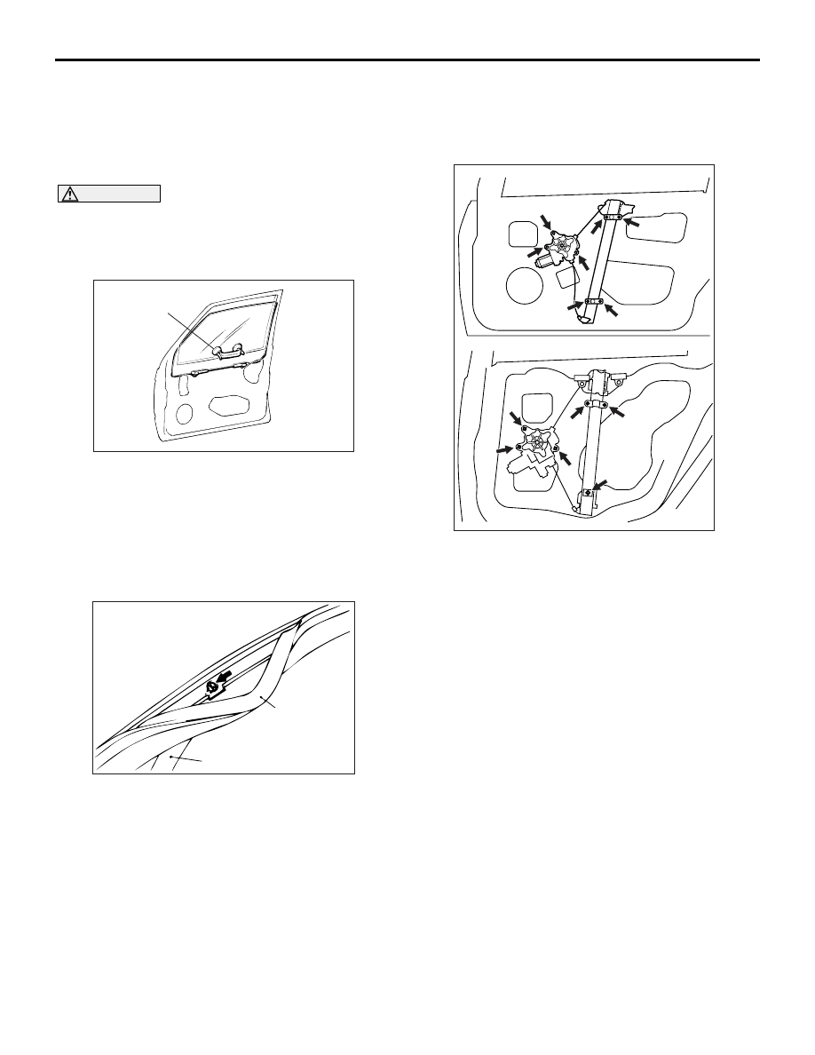
<<A>> WINDOW REGULATOR ASSEM-
BLY/POWER WINDOW REGULATOR 
MOTOR ASSEMBLY REMOVAL

1. Remove the door window glass installation bolts.

CAUTION

If film or others are adhered to the door window 
glass, attach special tool  window glass holder 
(MB990480) to the outside of the glass to prevent 
the film from peeling off.

AC100009AB

MB990480

2. Lift the door window glass, and attach special tool 

window glass holder (MB990480) to the glass as 
shown to prevent the glass from falling.

3. Remove the window regulator assembly and 

power window motor assembly

<<B>> CENTRE SASH UPPER REMOVAL

AC000602

Door outer 

opening

weatherstrip

Door centre

sash

AB

1. Remove the door outer opening weatherstrip from 

the centre sash upper only.

2. Remove the centre sash upper mounting screws, 

and then remove the centre sash upper from the 
door panel.

INSTALLATION SERVICE POINTS
>>A<< CENTRE SASH UPPER INSTALLA-
TION

Securely insert the centre sash upper into the win-
dow rear sash (door).

>>B<< WINDOW REGULATOR 
ASSEMBLY/POWER WINDOW 
REGULATOR MOTOR ASSEMBLY 
INSTALLATION

Y1536AU

Y1476AU

AC100010AB

<FRONT DOOR>

<REAR DOOR>

1

2

3

4

5

6

7

1

2

3

4

5

6

When installing the window regulator assembly, 
tighten the bolts to the specified torque in the order 
shown.

INSPECTION

M1429001400282

How to make the power window switch 
learn the fully closed position of the 
power window
How to make the power window switch 
learn the fully closed position when the 
power window switch is removed, or the 
power window regulator assembly is 
removed or replaced

1. If the anti-trap function (safety mechanism) is 

activated consecutively three times or more, the 
fully closed position that the power window switch 
has learned will be erased (initialised).

2. Operate the power window switch and fully open 

the door window glass.

DOOR

BODY

42-35

CAUTION

The anti-trap function does not work until the 
power window switch completes learning the 
fully closed position (It is because the anti-trap 
function is reset).
3. Operate the power window switch and fully close 

the door window glass. The power window 
activates for 0.7 seconds and stops automatically 
when the power window switch is pressed once. 
Repeat this operation until the door window glass 
fully closes and release the switch once. Then, 
hold the power window switch to the fully closed 
side again for one second so that the power 
window switch completes learning the fully closed 
position.
NOTE: If the power window switch is operated to 
open the door window glass while the switch is 
learning, learning will be cancelled. If this hap-
pens, return to step 2.

How to make the power window switch 
learn the fully closed position when the 
power window switch is replaced with a 
new one

CAUTION

The anti-trap function does not work until the 
power window switch completes learning the 
fully closed position (It is because the anti-trap 
function is reset).
Operate the power window main switch to fully close 
the door window glass by one-shot up action so that 
the power window switch will complete learning (Ini-
tialisation is not needed).
NOTE: When the power window sub switch of each 
seat is replaced, operate the power window main 
switch to fully close the applicable power window by 
one-shot up action (It is because the power window 
sub switch does not have one-shot up/down func-
tion).

DOOR

BODY

42-36

DOOR HANDLE AND LATCH

REMOVAL AND INSTALLATION

M1423004600328

Pre-removal Operation
• Door Trim Removal (Refer to GROUP 52A, Door trim 

P.52A-17

.)

Post-installation Operation
• Door Inside Handle Play Check (Refer to 

P.42-30

.)

• Door Outside Handle Play Check (Refer to 

P.42-29

.)

• Door Trim Installation (Refer to GROUP 52A, Door trim 

P.52A-17

.)

AC305110

<FRONT DOOR>

<REAR DOOR>

5

5.0 ± 1.0 N·m

1

4

9

2

AB

4

5

2

3

8

7

5.0 ± 1.0 N·m

1

6

9

N

N

8

9.0 ± 2.0 N·m

9.0 ± 2.0 N·m

Door handle and door latch assembly 
removal steps 

>>

C

<< 1. Door inside handle

• Waterproof film (Refer to 

P.42-39

.)

2. Door outside handle
3. Door lock key cylinder

>>

B

<< 4. Lower sash

5. Door latch assembly
6. Inside lock cable (Front door)
7. Inside lock rod (Rear door)
8. Inside handle rod
 Door check removal steps 
• Waterproof film (Refer to 

P.42-39

.)

>>

A

<< 9. Door check

INSTALLATION SERVICE POINTS
>>A<< DOOR CHECK INSTALLATION

ACX00541

Identification mark

AB

Install the door check so that the identification mark 
faces upwards.

Item

Identification 
mark

Front Door

Left door

39L

Right door

39R

Rear Door

Left door

40L

Right door

40R

DOOR

BODY

42-37

>>B<< LOWER SASH INSTALLATION

Securely insert the rear lower sash into the window 
rear sash.

>>C<< DOOR INSIDE HANDLE 
INSTALLATION

AC100404 AB

Clip

Inner cable

Outer cable end

Inside handle rod

Door inside handle

1. Install the inside lock cable to the door inside 

handle as follows:
(1) Install the inner cable end in the inside lock 

cable to the clip in the door inside handle.

(2) Turn the inside lock knob to the door lock 

position.

(3) Install the outer cable end to the door inside 

handle securely.

(4) Install the clip to the inner cable.

2. Install the inside handle rod to the door inside 

handle.

3. Install the door inside handle to the door.

INSPECTION

M1423004700392

FRONT DOOR LOCK ACTUATOR CHECK

4

2
5

3
6

1

4

2
5

3
6

1

AC305111

B

A

AB

Lock

Unlock

View A

View B

Unlock

Lock

Front door <Left side>

<Right side>

Lever

Lever

Actuator Operation Check 

Lever 
position

Battery connection Lever 

operation

At the 
"LOCK" 
position

• Connect terminal 

No. 4 and the 
negative battery 
terminal.

• Connect terminal 

No. 6 and the 
positive battery 
terminal.

The lever 
moves from the 
"LOCK" 
position to the 
"UNLOCK" 
position.

At the 
"UNLOCK" 
position

• Connect terminal 

No. 6 and the 
negative battery 
terminal.

• Connect terminal 

No. 4 and the 
positive battery 
terminal.

The lever 
moves from the 
"UNLOCK" 
position to the 
"LOCK" 
position.


Content   ..  226  227  228  229   ..