Mitsubishi Lancer. Manual - part 82
DASH PANEL
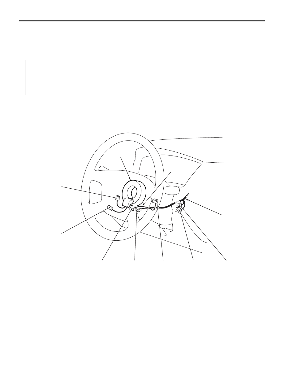
CONFIGURATION DIAGRAMS
80-30
DASH PANEL <LHD> (CONTINUED)
AC301179
Connector
symbol
-201
thru
-227
C
AB
STEERING COLUMN
C-207
C-206
C-201
C-202
C-203
C-203
C-204
C-205
Instrument panel
wiring harness
Clock spring
Y
C-201 (6)
Ignition switch
C-202 (7)
Key reminder switch
C-203 (10)
Column switch
C-204 (6)
Clock spring
C-205 (4-Y)
Clock spring
C-206 (1)
Horn switch
C-207 (2)
Air bag module (squib) <Driver’s side>
C-208 (13)
Instrument panel wiring harness and J/B
combination
C-209 (14)
Instrument panel wiring harness and J/B
combination
C-210 (6)
Instrument panel wiring harness and J/B
combination
C-211 (1-B)
Instrument panel wiring harness and J/B
combination
C-212 (28)
Instrument panel wiring harness and J/B
combination