Mitsubishi Lancer. Manual - part 71


  Index      Mitsubishi     Mitsubishi Lancer - service repair manual 2006 year


Search            


Content   ..  69  70  71  72   ..


Mitsubishi Lancer. Manual - part 71


OPERATIONS INSIDE THE VEHICLE

PERIODIC INSPECTION AND MAINTENANCE

2-20

4. If the clutch pedal height and clutch pedal clevis 

pin play are not within the standard value, loosen 
the setting nut to adjust the clutch pedal height 
and clevis pin play to the standard value.

CAUTION

Do not push in the master cylinder pushrod at 
this time, otherwise the clutch will not operate 
properly.

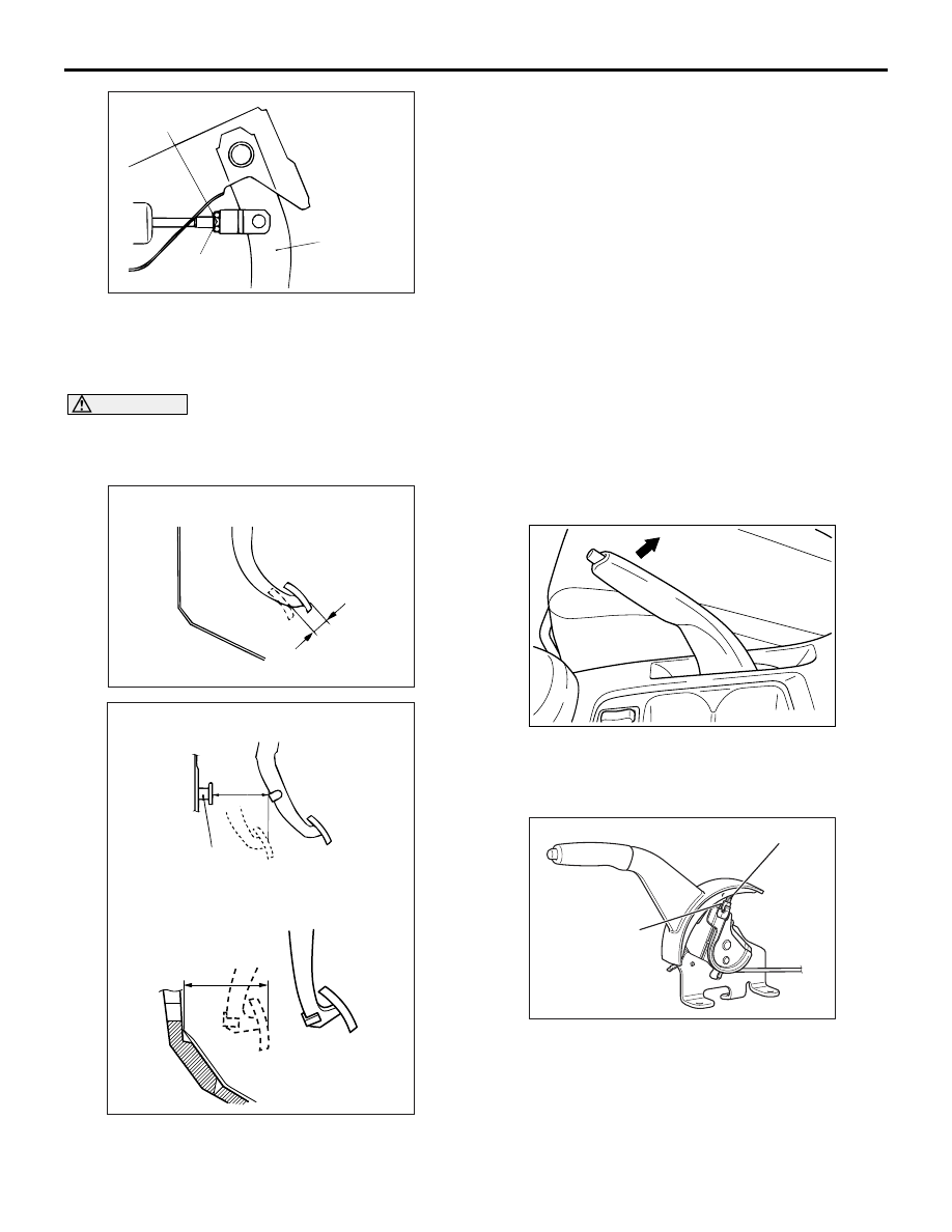
5. After completing the adjustments, confirm that the 

clutch pedal free play (measured at the face of the 
pedal pad) and the distance between the clutch 
pedal (the face of the pedal pad) and the clutch 
pedal stopper or dash pad when the clutch is 
disengaged are within the standard value ranges.
Standard value (C): 4 

 13 mm

Standard value (D): 105 mm or more

6. If the clutch pedal free play and the distance 

between the clutch pedal and the clutch pedal 
stopper or dash pad when the clutch is 
disengaged do not agree with the standard 
values, it is probably the result of either air in the 
hydraulic system or a faulty master cylinder, 
release cylinder or clutch. Bleed the air, or 
disassemble and inspect the master cylinder, 
release cylinder or clutch.

C2. CHECK PARKING BRAKE LEVER 
STROKE AND PLAY

M6020400200119

1. Pull the parking brake lever with a force of approx. 

200 N and count the number of notches.

Standard value: 5 

 7 notches

2. If the parking brake lever stroke is not the 

standard value, adjust as described below.
(1) Remove the floor console assembly. 
(2) Loosen the adjusting nut to move it to the 

cable rod end so that the cable will be free.

AC100356

Setting nut

Clutch pedal

13 ± 2 N·m

AB

AC100355 AC

C

Clutch pedal free play

AC310575

<LH drive vehicles>

Clutch pedal 
stopper

D

AB

<RH drive vehicles>

D

AC303998

AB

AC107239

Cable rod

Adjusting nut

AD

OPERATIONS INSIDE THE VEHICLE

PERIODIC INSPECTION AND MAINTENANCE

2-21

(3) Remove the rear brake adjusting hole plug. 

Then insert a flat-tipped screwdriver to turn the 
adjuster to the arrow direction (to expand the 
shoe) until the parking brake shoe makes 
contact and the disc can no longer be turned.


Back off the adjuster to the opposite direction 
by five notches.

(4) Adjust the parking brake lever stroke to the 

standard value by turning the adjusting nut. 
After the adjustment, ensure that there is no 
free play between the adjusting nut and the 
parking brake lever. 

CAUTION

If the parking brake lever stroke is below the 
standard value and the braking is too firm, the 
rear brakes may drag.

(5) After adjusting the parking brake lever stroke, 

jack up the rear end of the vehicle, and then 
release the parking brake and turn the rear 
wheels to check that the rear brakes are not 
dragging.

C3. REPLACE AIR PURIFIER FILTER

M6020400300086

1. Remove the glove box.
2. Remove the two screws as shown, and replace 

the air purifier filter.

3. Install the glove box.

AC202320AC

Adjuster

AC303997

AB

Air purifier filter

OPERATIONS OUTSIDE THE VEHICLE

PERIODIC INSPECTION AND MAINTENANCE

2-22

OPERATIONS OUTSIDE THE VEHICLE

D1. CHECK UNEVEN TYRE WEAR

M6020500100205

Check the entire periphery of the tyres for uneven 
wear. If any tyre shows uneven wear, check the toe-
in and toe-out, and adjust if necessary.
TOE-IN

Using a toe-in gauge, measure toe-in. 


Toe-in = B - A

Standard value: 

At the centre of tyre tread: 1 

± 2 mm

Toe angle (per wheel): 0

°03’± 0°06’

1. Adjust the toe-in by undoing the clip and lock nut, 

and turning the left and right tie rod turnbuckles by 
the same amount (in opposite directions).

NOTE: 


The toe will move out as the left turnbuckle is 
turned toward the front of the vehicle and the right 
turnbuckle is turned toward the rear of the vehicle.

2. Install the clip and tighten the lock nut to the 

specified torque.

Tightening torque: 40 

± 5 Nm

3. Confirm that the toe-in is at the standard value.

4. Use a turning radius gauge to check that the 

steering angle is at the standard value.

Standard value:

TOE-OUT ANGLE ON TURNS
To check the steering linkage, especially after the 
vehicle has been involved in an accident or if an acci-
dent is presumed, it is advisable to check the toe-out 
angle on turns in addition to the wheel alignment. 
Conduct this test on the left turn as well as on the 
right turn.

Standard value:

AC305666

AC102578

Lock nut

Clip

AE

Item

Specifications

Inner 
wheels

Invite

39

°30' ± 1°30'

Intense (L.H. 
drive vehicles)

33

°40' + 1°00'/−2°00’

Intense (R.H. 
drive vehicles)

37

°00' + 1°00'/−2°00’

Outer 
wheels 
(for 
reference)

Invite

32

°30'

Intense (L.H. 
drive vehicles)

28

°46'

Intense (R.H. 
drive vehicles)

30

°00'

Item

Specifications

Toe-out angle on turns (inner 
wheel when outer wheel at 20

°)

21

°42' ± 1°30'

AC306798

OPERATIONS OUTSIDE THE VEHICLE

PERIODIC INSPECTION AND MAINTENANCE

2-23

CAMBER, CASTER AND KINGPIN INCLINATION

Standard value:

NOTE: 

.

1. *: difference between right and left wheels must 

be less than 30'

2. Camber and caster are preset at the factory and 

cannot be adjusted.

3. For vehicles with aluminium wheels, attach the 

camber/caster/kingpin gauge to the driveshaft by 
using special tool wheel alignment gauge attach-
ment (MB991004). Tighten the special tool to the 
same torque 245 

±

 29 N

m as the driveshaft nut.

CAUTION

To prevent the wheel bearing from damage, never 
subject the wheel bearings to the vehicle load 
when the drive shaft nuts are loosened.

REAR TOE-IN

Standard value:

At the centre of tyre tread: 3 

± 2 mm

Toe angle (per wheel): 0

°08’ ± 0°05’

1. Be sure to adjust the camber before making toe 

adjustment.

2. Carry out adjustment by turning the toe adjusting 

bolt (control link mounting bolt which is located on 
the inner side of the body).

Left wheel: Turning clockwise (+) toe-in
Right wheel: Turning clockwise (

) toe-in

NOTE: 


The scale has gradations of approximately 2.6 
mm (single side toe angle equivalent to 16')

CAUTION

To prevent bushings from breakage, the control 
link mounting nut should be temporarily tight-
ened, and then fully tightened to 120 

± 10 N

with the vehicle on the ground in the unladen 
condition.

REAR CAMBER

Standard value: 

0°40' ± 0°30'

(Left / right deviation within 30')

NOTE: For vehicles with aluminium wheels, attach 
the camber/caster/kingpin gauge to the trailing arm 
spindle by using special tool wheel alignment gauge 
attachment (MB991014). Tighten the special tool to 
the same torque. 175 

±

 25 N

m as the rear wheel hub 

nut (self-locking nut).

If camber is not within the standard value, adjust by 
following procedures.
1. Disconnect the conjunction of the control link and 

the trailing arm.

Item

Specifications
Invite

Intense

Camber

0

°05' ± 0° 30'*

−0°05' ± 0° 30'*

Caster

2

°45' ± 0° 30'*

2

°55' ± 0° 30'*

Kingpin 
inclination

12

°30' ± 1°30'

12

°40' ± 1°30'

AC001079

MB991004

AB

AC102499

Toe adjusting bolt

Control link

Control link

120 ± 10 N·m

AD

AC001079

MB991014

AG

<Vehicles with aluminium wheels>

AC006159 AC

Camber adjusting bolt

Lower arm 
assembly


Content   ..  69  70  71  72   ..