Mitsubishi Lancer. Manual - part 72
OPERATIONS OUTSIDE THE VEHICLE
PERIODIC INSPECTION AND MAINTENANCE
2-24
2. Carry out adjustment by turning the camber
adjusting bolt (lower arm assembly mounting bolt
which is located on the inner side of the body).
Left wheel: Turning clockwise (+) camber
Right wheel: Turning clockwise (
−) camber
NOTE:
The scale has gradations of approximately 14’.
3. Tighten the control link to the trailing arm.
CAUTION
To prevent bushings from breakage, the connect-
ing bolt should be temporarily tightened, and
then fully tightened to 90
± 10 N⋅m with the vehi-
cle on the ground in the unladen condition.
4. After adjusting the camber, the toe should be
adjusted.
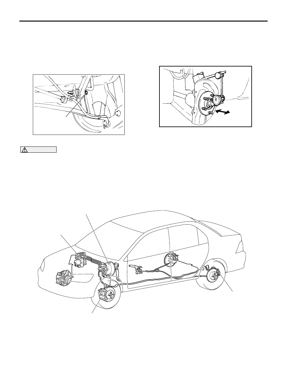
D2. CHECK FRONT WHEEL BEARINGS
FOR PLAY
M6020500200020
1. Remove the disc brake caliper and suspend it
with a wire.
2. Remove the brake disc from the front hub.
3. Attach a dial gauge as shown in the illustration,
and then measure the axial play while moving the
hub in the axial direction.
Limit: 0.05 mm
4. If axial play exceeds the limit, replace the front
hub assembly.
D3. CHECK BRAKE HOSES AND PIPES
FOR LEAKAGE
M6020500300072
1. Check entire circumference and length of hoses
and pipes.
2. Check all clamps for tightness and connections
for leakage.
AC006160 AC
Connecting bolt
AC102438AD
AC304027AC
Rear disc brake
Front disc brake
Brake booster assembly
Brake modulator
hydraulic unit