Mitsubishi Lancer. Manual - part 69


  Index      Mitsubishi     Mitsubishi Lancer - service repair manual 2006 year


Search            


Content   ..  67  68  69  70   ..


Mitsubishi Lancer. Manual - part 69


OPERATIONS INSIDE THE ENGINE COMPARTMENT

PERIODIC INSPECTION AND MAINTENANCE

2-12

4. When the engine coolant has drained, pour in 

water from the radiator cap to clean the engine 
coolant line.

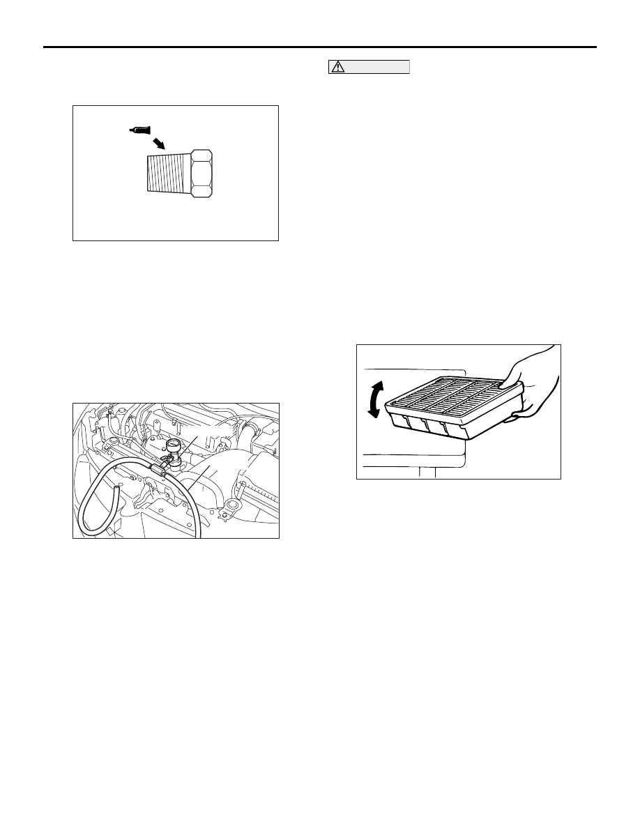
5. Coat the thread of the cylinder block drain plug 

with the specified sealant and tighten to the 
specified torque.

Specified sealant: 3M Nut Locking Part 
No.4171 or equivalent
Tightening torque:

40 

± 5 Nm <4G1>

44 

± 5 Nm <4G6>

6. Securely tighten the radiator drain plug.
7. Install the reserve tank.

8. By referring to the section on coolant, select an 

appropriate concentration for safe operating 
temperature within the range of 30 to 60%. Use 
special tool LLC changer (MB991871) to refill the 
coolant. A convenient mixture is a 50% water and 
50% antifreeze solution (freezing point: 

−31°C)

NOTE: For How to use special tool MB991871, 
refer to its manufacturer’s instructions.

Recommended antifreeze: DIA QUEEN 
SUPER LONG LIFE COOLANT or equivalent
Quantity:

5.0L <4G1>
7.0L <4G6>

CAUTION

Do not use alcohol or methanol anti-freeze or any 
engine coolants mixed with alcohol or methanol 
anti-freeze. The use of an improper anti-freeze 
can cause the corrosion of the aluminium com-
ponents.
9. Install the radiator cap securely.
10.Start the engine and warm the engine until the 

thermostat opens. (Touch the radiator hose with 
your hand to check that warm water is flowing.)

11.After the thermostat opens, race the engine 

several times, and then stop the engine.

12.Cool down the engine, and then pour engine 

coolant into the reserve tank until the level 
reaches the FULL line. If the level is low, repeat 
the operation from step 10.

A12. CHECK AIR CLEANER ELEMENT 
FOR CLOGGING AND DAMAGE

M6020201200022

1. Check air cleaner element for clogging and 

damage.

2. Clean deposited dust from the element in the 

following manner.
(1) Lightly tap the element against the top of a 

bench.

(2) Blow compressed air from inside the element.

3. Wipe off dust on the air cleaner interior.
4. Install the air cleaner body.

A13. REPLACE AIR CLEANER ELEMENT

M6020201300029

The air cleaner element will become dirty and loaded 
with dust during use, and the filtering effect will be 
substantially reduced. Replace it with a new one.

AC104528AE

AC210658AB

MB991871

Air hose

AC305657

OPERATIONS INSIDE THE ENGINE COMPARTMENT

PERIODIC INSPECTION AND MAINTENANCE

2-13

1. Unclasp the air cleaner cover clip.
2. Remove the air cleaner element and install a new 

one.

3. Be sure to close the air cleaner cover completely 

when clamping it.

A14. CHECK FLUID LEVEL IN BRAKE 
RESERVOIR AND CLUTCH RESERVOIR 
(for hydraulic-type clutch only)

M6020201400026

1. Check that the fluid level is between the "MAX" 

and "MIN" or "A" mark.

2. If it is below the "MIN" or "A" marks, replenish with 

fresh brake fluid up to the "MAX" mark.

A15. CHANGE BRAKE FLUID

M6020201600194

1. Remove the cap of the bleeder screw, connect a 

vinyl tube, and place its other end in a receptacle.

2. Loosen the bleeder screw and depress the brake 

pedal; supply new brake fluid when the level of 
the fluid within the reservoir tank decreases.

CAUTION

If the reservoir tank completely runs out of fluid 
during operation, air will find way into the brake 
line. Pay attention, therefore, to the fluid level 
and replenish as necessary.

Specified brake fluid: DOT3 or DOT4

CAUTION

Use the specified brake fluid. Avoid using a mix-
ture of the specified brake fluid and other fluid. If 
brake fluid is exposed to the air, it will absorb 
moisture; as water is absorbed from the atmos-
phere, the boiling point of the brake fluid will 
decrease and the braking performance will be 
seriously impaired. For this reason use a hermet-
ically sealed 1 L. or 0.5 L. brake fluid container. 
Firmly close the cap of the brake fluid container 
after use.
3. When fresh fluid has come to flow out from the 

vinyl tube, tighten the bleeder screw.
NOTE: 


This change from existing to fresh fluid can be 
judged by change in color of fluid that flows out.

4. Repeat above steps for other bleeder screws.

NOTE: 


The operating steps for each bleeder screws are 
illustrated on this page.

MASTER CYLINDER BLEEDING

The master cylinder used has no check valve, so if 
bleeding is carried out by the following procedure, 
bleeding of air from the brake pipeline will become 
easier. (When brake fluid is not contained in the mas-
ter cylinder.)
1. Fill the reserve tank with brake fluid.
2. Keep the brake pedal depressed.

AC210259

Air cleaner element

AD

AC305658

AC305659

AC305660

( ):R.H. drive vehicle

AB

OPERATIONS INSIDE THE ENGINE COMPARTMENT

PERIODIC INSPECTION AND MAINTENANCE

2-14

3. Have another person cover the master cylinder 

outlet with a finger.

4. With the outlet still closed, release the brake 

pedal.

5. Repeat steps (2) - (4) three or four times to fill the 

inside of the master cylinder with brake fluid.

A16. CHECK BATTERY ELECTROLYTE 
LEVEL

M6020201700210

1. Inspect whether or not the battery fluid is between 

the UPPER LEVEL and LOWER LEVEL marks.

CAUTION

1. If the battery fluid is below the LOWER 

LEVEL, the battery could explode in using.

2. If the battery fluid is over the UPPER LEVEL, 

leakage could result.

2. Use a hydrometer and thermometer to check the 

specific gravity of the battery fluid.

Standard value: 1.220 

 1.290 [20°C]

3. The specific gravity of the battery fluid varies with 

the temperature, so use the following formula to 
calculate the specific gravity for 20

°C. Use the 

calculated value to determine whether or not the 
specific gravity is satisfactory.

D20 = (t  -  20) 

×  0.0007 + Dt

D20: Specific gravity of the battery fluid cal-
culated for 20

°C.

t: Actually measured temperature
Dt: Actually measured specific gravity

A18. REPLACE FUEL FILTER

M6020201900106

1. Remove the rear seat cushion assembly.
2. Remove the service hole cover mounting screws 

and remove the service hole cover.

3. Disconnect the fuel tank pump assembly 

connector, fuel high-pressure hose and fuel tank 
hose.

4. Remove the mounting nuts and fuel pump bracket 

plate, and remove the fuel pump assembly from 
the service hole.

AC000876AD

AC504567

AB

Battery fluid

Thermometer Hydrometer

AC303087AB

Fuel high-pressure
hose

Fuel tank hose

Fuel tank pump connector

OPERATIONS INSIDE THE ENGINE COMPARTMENT

PERIODIC INSPECTION AND MAINTENANCE

2-15

5. Install the fuel pump assembly to the fuel tank 

through the service hole.

6. Install the fuel pump bracket plate to the fuel tank 

and tighten the mounting nuts to the specified 
torque.

Tightening torque: 2.5 

± 0.5 Nm

7. Connect the fuel tank pump assembly connector, 

fuel high-pressure hose and fuel tank hose.

CAUTION

After connecting the fuel high-pressure hose, 
slightly pull it to ensure that it is installed 
securely. Also confirm that there is a play 
approximately 3 mm.
8. Tighten the service hole cover mounting screws 

and install the service hole cover.

9. Install the rear seat cushion assembly.

AC303094

N

N

Fuel filter assembly
(Replace fuel filter assembly)

AC

FUEL PUMP MODULE

O-ring

Grommet

Fuel pump

Suction filter
(Not replace suction filter)

AC303087AB

Fuel high-pressure
hose

Fuel tank hose

Fuel tank pump connector

AC300047

3 mm

AD

Fuel high-pressure hose

Corresponding side

Quick connector


Content   ..  67  68  69  70   ..