Mitsubishi Lancer. Manual - part 56


  Index      Mitsubishi     Mitsubishi Lancer - service repair manual 2006 year


Search            


Content   ..  54  55  56  57   ..


Mitsubishi Lancer. Manual - part 56


PRE-DELIVERY INSPECTION --

Operations inside the Vehicle

2-24

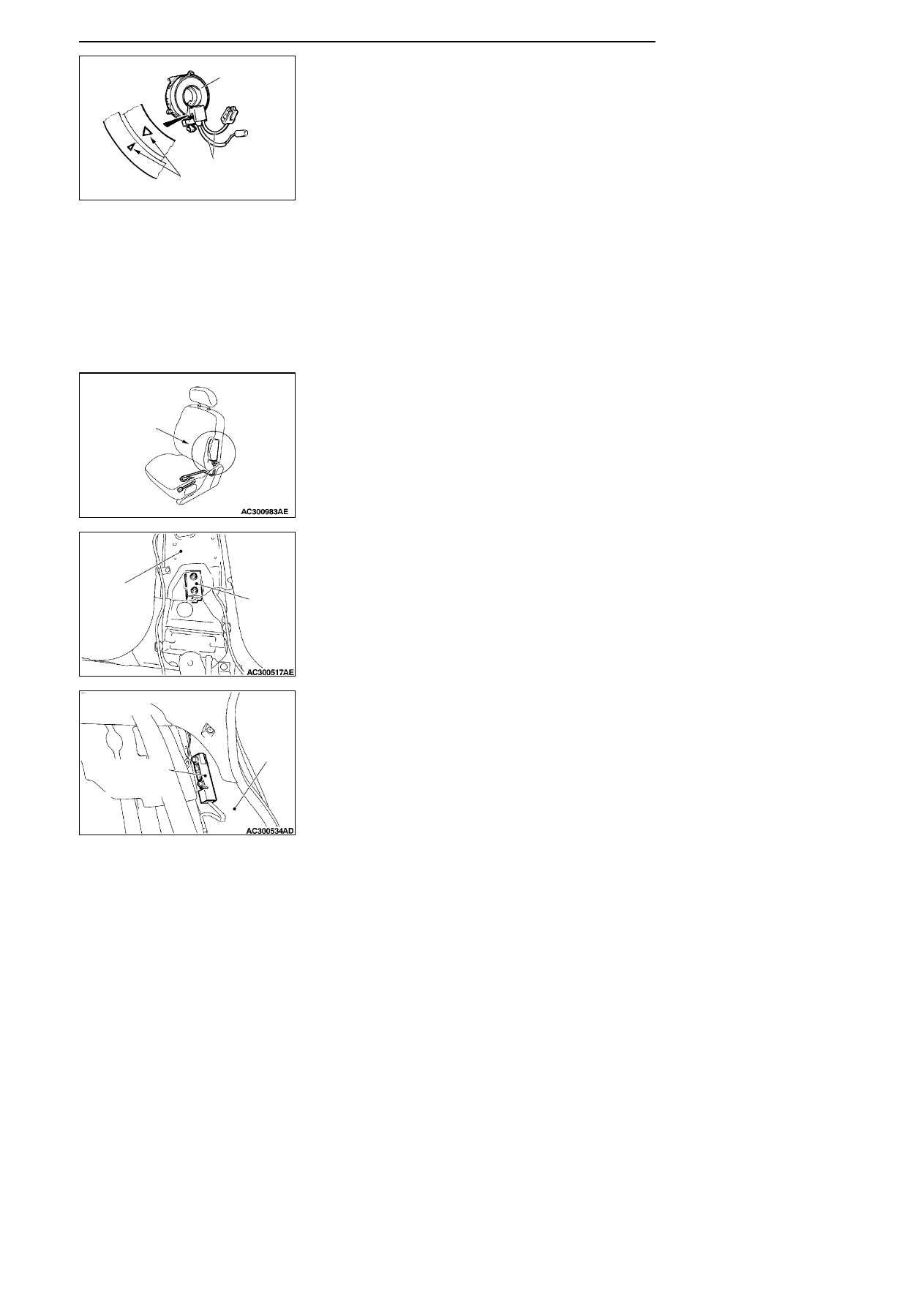
(8) Align the mating marks of the clock spring, and after

turning the vehicle’s front wheels to straight-ahead
position, install the clock spring to the column switch.

Mating Mark Alignment

Turn the clock spring clockwise fully, and then turn it
back approx. 3 3/4 turns counterclockwise to align the
mating marks.
Caution
If the clock spring’s mating mark is not properly
aligned, the steering wheel may not be completely
rotational during a turn, or the flat cable within the
clock spring may be severed, obstructing normal op-
eration of the SRS and possibly leading to serious
injury to the vehicle’s driver or front passenger.

(9) Install the steering column covers, steering wheel and

the air bag module.

(10)Check steering wheel for noise, binds of difficult

operation.

(11)Check steering wheel for excessive free play.

Caution
The SRS may not activate if any of the above compo-
nents is not installed properly, which could result in
serious injury or death to the vehicle’s driver or front
passenger.

FRONT SEATBACK ASSEMBLY WITH SIDE AIR BAG
MODULE

(1) Check the side air bag module deployment section in the

seat for dents and deformation.

(2) Check the harness for binds, the connector for damage

and the terminals for deformation.

SIDE IMPACT SENSORS

FRONT

(1) Check the center piller for deformation or rust.
(2) Check the side impact sensors for dents, cracks,

deformation or rust.

(3) Check the connectors for damage and the terminals for

deformation.

REAR

(1) Check the quarter panel inner for deformation or rust.
(2) Check the side impact sensors for dents, cracks,

deformation or rust.

(3) Check the connectors for damage and the terminals for

deformation.

AC100446AD

Case

Protective tubes

Mating mark

Air bag module
deployment
section

Side
impact
sensor

(Front)

Center
pillar

Quarter
panel
inner

Side impact
sensor (Rear)

PRE-DELIVERY INSPECTION --

Operations inside the Vehicle

PRE-DELIVERY INSPECTION --

Operations inside the Vehicle

2-25

CURTAIN AIR BAG MODULE

(1) Check the curtain air bag module deployment section in

the headlining for dents and deformation.

(2) Check the inflator surface for cracks, dents, and

deformation.

(3) Check the harness for binds, the connector for damage

and the terminals for deformation.

SEAT BELT WITH PRE-TENSIONER

(1) Check the seat belt pre-tensioner for dents or

deformation.

(2) Check that the seat belt pre-tensioner is installed

correctly to the vehicle body.

INSTRUMENT PANEL WIRING HARNESS/FLOOR WIRING HARNESS/ROOF WIRING

HARNESS

Air bag module connector

Clock spring connector

Instrument panel
wiring harness

Air bag module connector

Instrument panel
wiring harness

SRS-ECU connector

Curtain air bag module
deployment section

PRE-DELIVERY INSPECTION --

Operations inside the Vehicle

2-26

Side impact sensor connector
(Front : RH)

Side air bag module
connector (RH)

Curtain air bag
module connector (RH)

Curtain air bag
module connector (LH)

Roof wiring harness

Seat belt pre-tensioner connector (RH)

Side impact sensor
connector (Rear : RH)

Side impact sensor connector
(Rear : LH)

Side impact sensor connector
(Front : LH)

Seat belt pre-tensioner connector (LH)

Side air bag module connector

(LH)

Floor wiring harness

Instrument panel
wiring harness

(1) Check connector for poor connection.
(2) Check harnesses for binds, connectors for damage, and

terminals for deformation.
REPLACE ANY CONNECTORS OR HARNESS THAT
FAIL THE VISUAL INSPECTION.

Caution
The SRS may not activate if SRS harnesses or con-
nectors are damaged or improperly connected,
which could result in serious injury or death to the
vehicle’s driver or front passenger.

POST-INSTALLATION INSPECTION

Reconnect the negative battery terminal. Turn the ignition
key to the ON position. Does the SRS warning lamp
illuminate for about 7 seconds, turn off and then remain
extinguished for at least 5 seconds? If yes, SRS system is
functioning properly.

SRS warning lamp

PRE-DELIVERY INSPECTION --

Operations outside the Vehicle

2-27

OPERATIONS OUTSIDE THE VEHICLE

D1.

CHECK UNEVEN TYRE WEAR

Check the entire periphery of the tyres for uneven wear.
If any tyre shows uneven wear, check the toe-in and toe-out,
and adjust as necessary.

TOE-IN

Using a toe-in gauge, measure toe-in.
Toe-in = B -- A

Standard value:

At the centre of tyre tread: 1

±

2 mm

Toe angle (per wheel): 0

_ 03’

±

06’

(1) Adjust the toe-in by undoing the clip and lock nut, and

turning the left and right tie rod turnbuckles by the same
amount (in opposite directions).

NOTE
The toe will move out as the left turnbuckle is turned to-
ward the front of the vehicle and the right turnbuckle is
turned toward the rear of the vehicle.

(2) Install the clip and tighten the lock nut to the specified

torque.

Tightening torque: 40

± 5 N·m

(3) Confirm that the toe-in is at the standard value.
(4) Use a turning radius gauge to check that the steering

angle is at the standard value.

Standard value:

Item

Specifications

Inner

h

l

Comfort

39

_30’ ± 1_30’

wheels

Sport (L.H.
drive vehicles)

33

_40’ + 1_00’/-2_00’

Sport (R.H.
drive vehicles)

37

_00’ + 1_00’/-2_00’

Outer

h

l

Comfort

32

_30’

wheels
(reference)

Sport (L.H.
drive vehicles)

28

_46’

Sport (R.H.
drive vehicles)

30

_00’

AC102578AD

Clip

Lock nut


Content   ..  54  55  56  57   ..