Mitsubishi Lancer. Manual - part 22
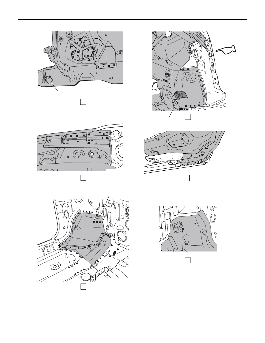
FENDER SHIELD
WELDED PANEL REPLACEMENT
3-6
AB301042
Y0189AV
E
F
I
G
H
AB
(Right side)
2 points right side only
High-rigidity foam
(LHD left side)
4 points, passenger's side only
(With the upper frame extension outer removed)
I
I