Mitsubishi Lancer. Manual - part 17
TYPE A (PROJECTED DIMENSIONS)
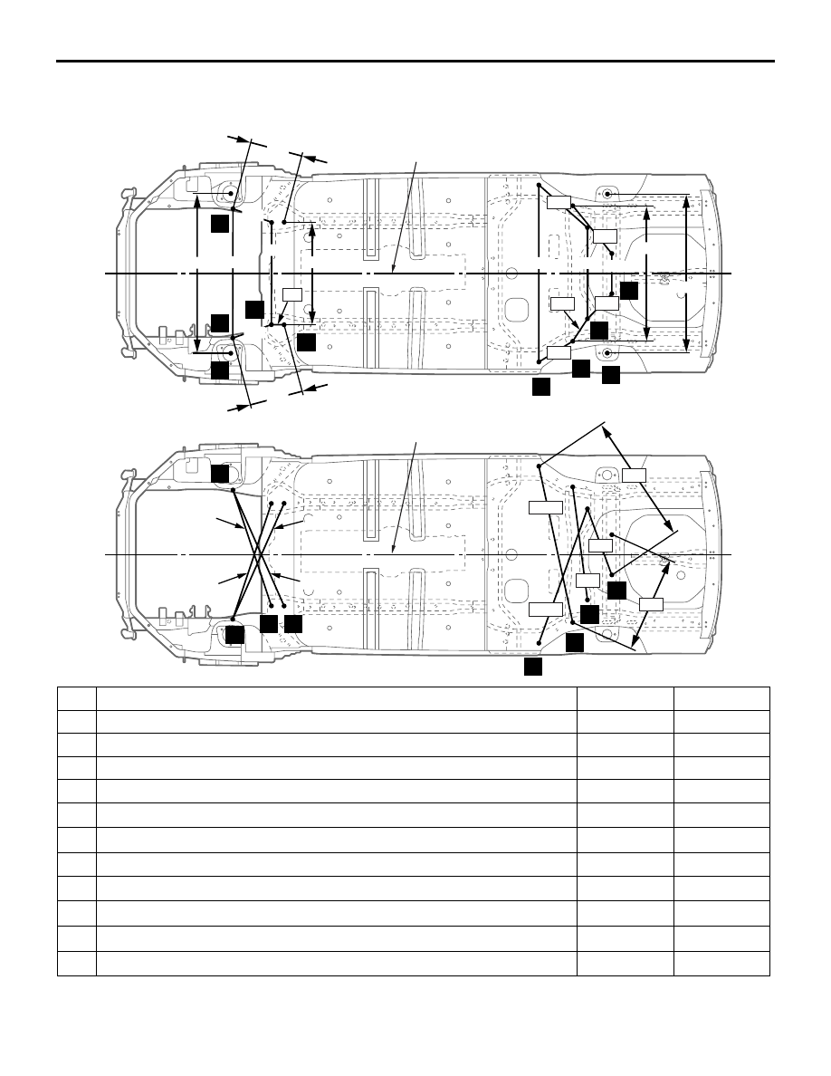
BODY DIMENSIONS
2-24
SUSPENSION INSTALLATION
DIMENSIONS <WAGON>
M4020013000304
AB300576
AB
mm
12
11
10
3
8
9
14
15
16
13
372
290
713
713
906
288
370
1,111
1,110
1,201
350
880
650
154
368
514
373
219
86
Centre line of the vehicle
AB300577
AB
3
10
12
11
16
13
14
15
1,092
857
882
851
888
772
977
525
669
1,022
Centre line of the vehicle
No. Standard measurement point
Hole shape Size mm
3
Centre of front crossmember mounting hole
Round
18
4
Centre of front floor sidemember positioning hole
Round
25
8
Centre of front shock absorber mounting hole
Round
114
9
Centre of rear shock absorber mounting hole
Round
64
10
Tip of crossmember mounting bolt (left)
−
−
11
Tip of front crossmember mounting bolt (right)
−
−
12
Centre of front crossmember mounting hole
Round
11
13
Centre of trailing arm mounting position
−
−
14
Centre of control link mounting hole
−
−
15
Centre of upper arm mounting position
−
−
16
Centre of lower arm mounting position
−
−