Mitsubishi Lancer. Manual - part 12
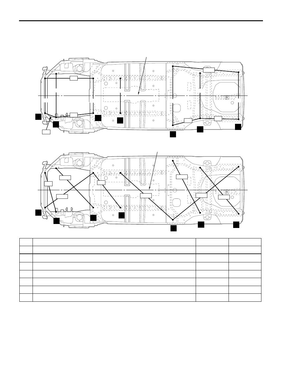
TYPE A (PROJECTED DIMENSIONS)
BODY DIMENSIONS
2-4
TYPE A (PROJECTED DIMENSIONS)
UNDER BODY <SEDAN>
M4020005000279
AB300566
1
2
3
4
5
6
7
AB
mm
750
1,010
982
786
713
714
1,220
926
963
582
795
1,364
247
(Centre line of the vehicle)
AB300567
AB
1
2
3
4
5
6
7
905
1,157
1,225
1,462
1,212
1,742
1,234
909
(Centre line of the vehicle)
No. Standard measurement point
Hole shape Size mm
1*
Centre of under cover mounting hole
Round
8
2
Front sidemember inner notch
−
−
3*
Centre of front crossmember mounting hole
Round
18
4*
Centre of front floor sidemember positioning hole
Round
25
5*
Centre of rear seat crossmember side water draining hole
Oblong
22
× 38
6
Centre of rear floor sidemember water draining hole
Round
16
7*
Centre of trailer bar mounting hole
Round
15
NOTE: The * mark indicates the mounting position for the frame centering gauge.