Mitsubishi Lancer (4A9 engine). Manual - part 243
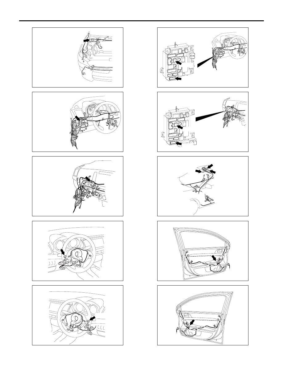
ACA00897
AB
A-78 (B)
Connector: A-78
ACA00891
AB
Connector: C-63 <LHD>
ACA00896
AB
Connector: C-63 <RHD>
AC612708
Connector: C-201 <LHD>
AT
AC612716 AK
Connector: C-201 <RHD>
C-201
ACA00886
AG
Connectors: C-301, C-316 <LHD>
ETACS-ECU
C-301
C-316
ACA00887
AG
Connector: C-301, C-316 <RHD>
ETACS-ECU
C-316
C-301
ACA00898
Connectors: D-02, D-06, D-45
D-02
D-45 (B)
AC
D-06 (GR)
AC612730
Connector: E-14 <LHD>
AH
AC612735
Connector:E-14 <RHD>
AF
TROUBLESHOOTING
LOCAL INTERCONNECT NETWORK (LIN)
54B-23