Mitsubishi Lancer (4A9 engine). Manual - part 210


  Index      Mitsubishi     Mitsubishi Lancer (4A9 engine) 12GS41 & 44S - service repair manual


Search            


Content   ..  208  209  210  211   ..


Mitsubishi Lancer (4A9 engine). Manual - part 210


DC/DC CONVERTER <VEHICLES WITH AUTO STOP & GO (AS&G) SYSTEM>

CHASSIS ELECTRICAL

54A-502

STEP 7. Check the wiring harness between C-65 
DC/DC converter connector terminal No.9 and 
fusible link (36) <Petrol> or (38) <Diesel>.

• Check the power supply line for open circuit and 

short circuit.

Q: Is the check result normal?

YES : 

The trouble can be an intermittent 

malfunction (Refer to GROUP 00, How to 
use Troubleshooting/inspection Service 
Points, How to Cope with Intermittent 
Malfunction ).

NO : 

Repair the wiring harness.

STEP 8. Resistance measurement at C-65 DC/DC 
converter connector.
(1) Disconnect the connector, and measure at the 

wiring harness side.

(2) Check the continuity between terminal No.10 and 

earth.

OK: Continuity exists (2 

 or less)

Q: Is the check result normal?

YES : 

No action is necessary and testing is 

complete.

NO : 

Go to Step 9.

STEP 9. Check the wiring harness between C-65 
DC/DC converter connector terminal No.10 and 
body earth.

• Check the body earth wires for open circuit.

Q: Is the check result normal?

YES : 

The trouble can be an intermittent 

malfunction (Refer to GROUP 00 

− How to 

use Troubleshooting/inspection Service 
Points 

− How to Cope with Intermittent 

Malfunction ).

NO : 

Repair the wiring harness.

Inspection Procedure 2: Audio equipment is reset or sound jump occurs at auto start.

CAUTION

Even when the diagnosis code No. B1301 or B1302 is set in the AS&G-ECU, do not conclude as a DC/
DC converter or AS&G-ECU error, and be sure to check the DC/DC converter power supply circuit.

COMMENTS ON TROUBLE SYMPTOM
If a reset or sound jump occurs with the AUDIO 
equipment at the auto start, the following causes can 
be suspected.

• Diagnosis code No. B1301 or B1302 is stored in 

AS&G-ECU, and voltage is not boosted by DC/
DC converter at auto start

• DC/DC converter internal malfunction

• Battery voltage drop

• Communication error with AS&G-ECU and DC/

DC converter

• AS&G-ECU malfunction

NOTE: If a reset or sound jump occurs with AUDIO 
equipment at other than the auto start, a problem is 
present with the power supply to the equipment that 
experienced the reset or sound jump. Therefore, be 
sure to check the power supply to the equipment.

PROBABLE CAUSES

• The DC/DC converter may be defective.

• The AS&G-ECU may be defective.

• The battery may be defective.

• Damaged harness wires and connectors

DIAGNOSIS PROCEDURE

STEP 1. Check the power supply system circuit
Check the DC/DC converter power supply circuit by 
referring to Troubleshooting. (Refer to .)

Q: Is the check result normal?

ACA00895AQ

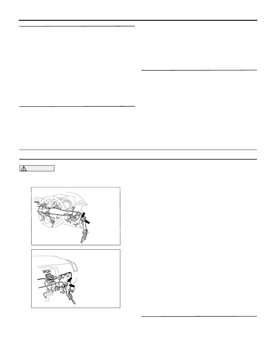
Connector: C-64, C-65 <RHD>

C-65 (GR)

C-64

ACA00892

Connectors: C-64, C-65 <LHD>

AQ

C-64

C-65 (GR)

DC/DC CONVERTER <VEHICLES WITH AUTO STOP & GO (AS&G) SYSTEM>

CHASSIS ELECTRICAL

54A-503

YES : 

Go to Step 2.

NO : 

Repair according to the troubleshooting, 
and recheck the trouble symptom.

STEP 2. Check the M.U.T.-III Diagnosis code for 
other systems
Check if the diagnosis code No. B1301 or B1302 is 
set to AS&G-ECU.

Q: Is the diagnosis code set?

YES : 

Erase the diagnosis code, and then go to 

Step 3.

NO : 

Go to Step 3.

STEP 3. Check the M.U.T.-III Diagnosis code for 
other systems
Check if the diagnosis code is set to AS&G-ECU.

Q: Is the diagnosis code set?

YES : 

Diagnose the AS&G-ECU (Refer to GROUP 

17 

− Troubleshooting ).

NO : 

Go to Step 4.

STEP 4. Battery test
Check the battery state.(Refer to .)

Q: Is the check result normal?

YES<Except vehicles with MMCS> : 

Go to Step 7.

YES<Vehicles with MMCS> : 

Go to Step 5.

NO : 

Replace the battery

STEP 5. Connector check: C-128 intermediate 
connector

Q: Is the check result normal?

YES : 

Go to Step 6.

NO : 

Repair the defective connector.

STEP 6. Check the wiring harness between C-65 
DC/DC converter connector terminal No.8 and C-
128 intermediate connector terminal No.1.

• Check the signal lines for open circuit and short 

circuit.

Q: Is the check result normal?

YES : 

Go to Step 7.

NO : 

Repair the wiring harness.

STEP 7. Replace the DC/DC converter 
temporarily, and check the trouble symptom.

Q: Is the check result normal?

YES : 

Replace the DC/DC converter.

NO : 

Replace the AS&G-ECU.

DC/DC CONVERTER REMOVAL AND INSTALLATION

M1549700700028

INSPECTION

DC/DC CONVERTER INSPECTION

M1549700900011

1. Remove the DC/DC converter. (Refer to )

2. Check that the continuity exists

Pre-removal operation
• Removal of instrument panel lower (Refer to GROUP 52A 

- Instrument Lower Panel ) <RHD>

• Removal of glove box (Refer to GROUP 52A - Glove Box 

) <LHD>

Post-installation operation
• Installation of instrument panel lower (Refer to GROUP 

52A - Instrument Lower Panel ) <RHD>

• Installation of glove box (Refer to GROUP 52A - Glove 

Box ) <LHD>

AC905309

5.0 ± 2.0 N·m

DC/DC converter

AC

Front deck crossmember

DC/DC CONVERTER <VEHICLES WITH AUTO STOP & GO (AS&G) SYSTEM>

CHASSIS ELECTRICAL

54A-504

AC905384 AB

Tester connection 

Measurement value

− 7

Continuity exists (2 

Ω or 

less)

DEFOGGER

CHASSIS ELECTRICAL

54A-505

DEFOGGER

SPECIAL TOOLS

M1547000600350


Content   ..  208  209  210  211   ..